Miter saw having two laser oscillators

a laser oscillator and miter saw technology, applied in the field of miter saws, can solve the problems of degrading cutting efficiency and degrading the visibility of the cutting lin

Inactive Publication Date: 2006-03-02
HITACHI KOKI CO LTD
View PDF27 Cites 48 Cited by
  • Summary
  • Abstract
  • Description
  • Claims
  • Application Information

AI Technical Summary

Benefits of technology

[0005] It is therefore, an object of the present invention to provide a miter saw capable of providing a clear laser

Problems solved by technology

However, the marking line may be covered with cutting chips and becomes invisible, to degrade cutting efficiency.
However, if the upper surface contains

Method used


Image

  • Miter saw having two laser oscillators
  • Miter saw having two laser oscillators
  • Miter saw having two laser oscillators

Examples


first embodiment

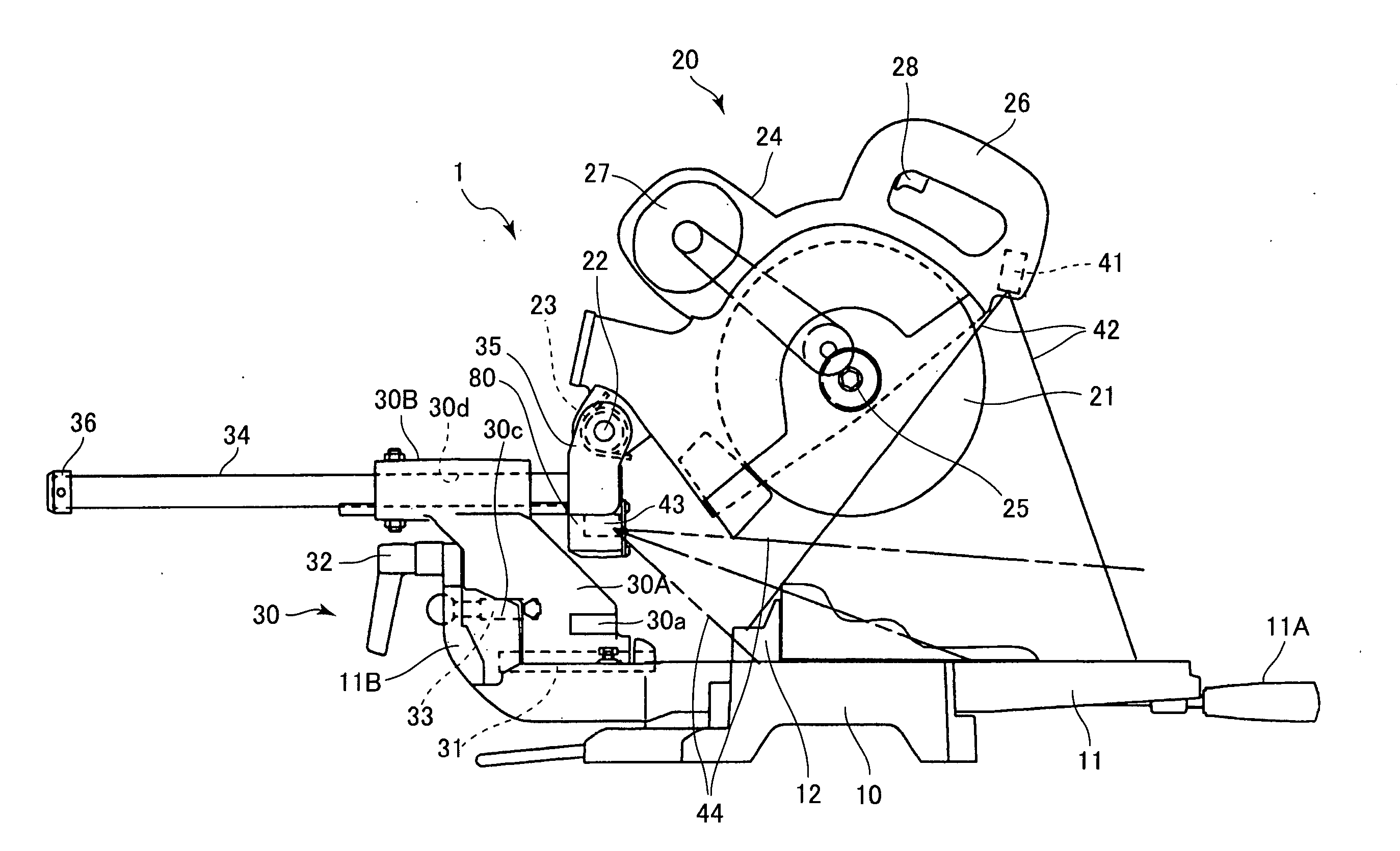
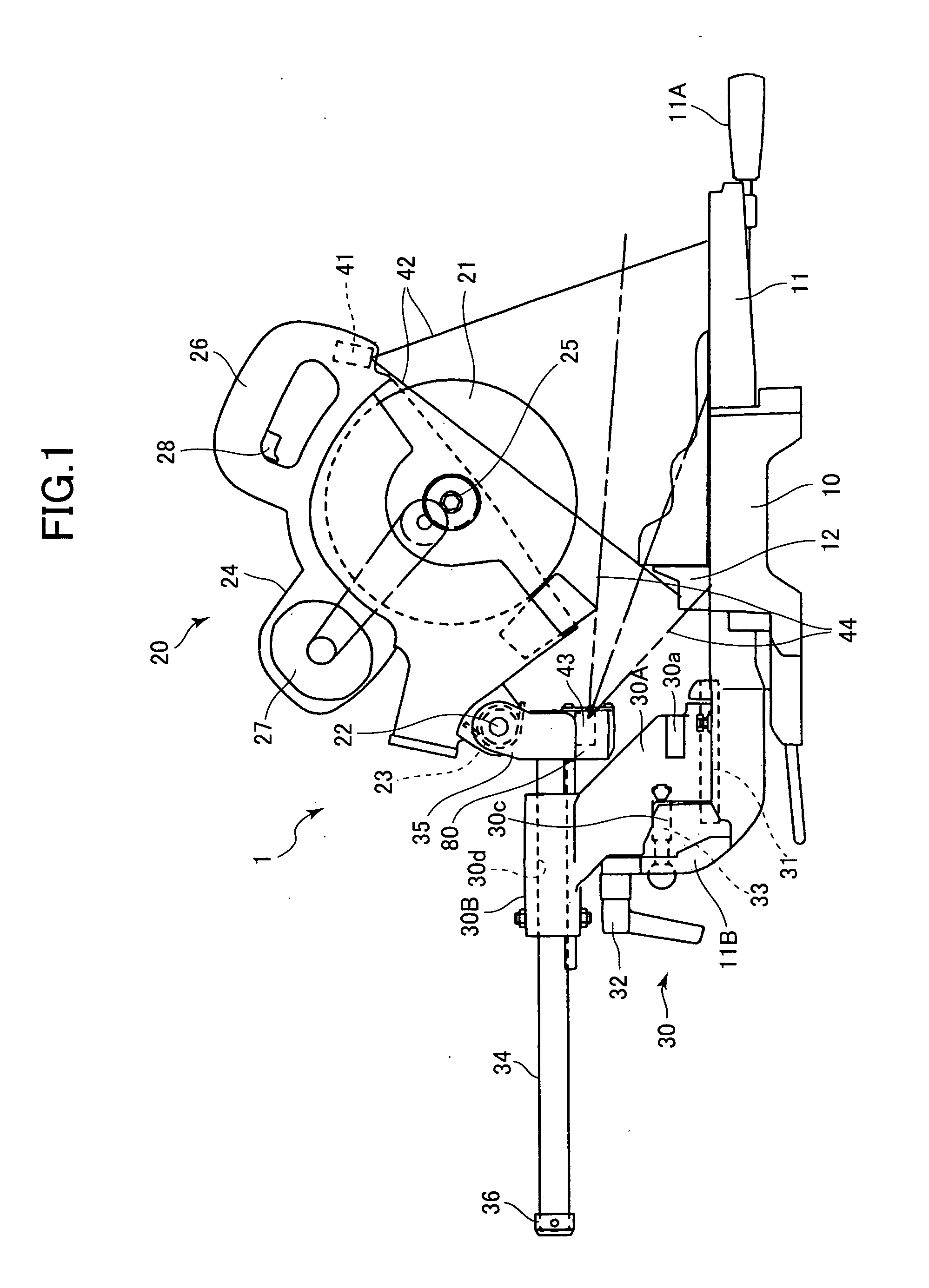
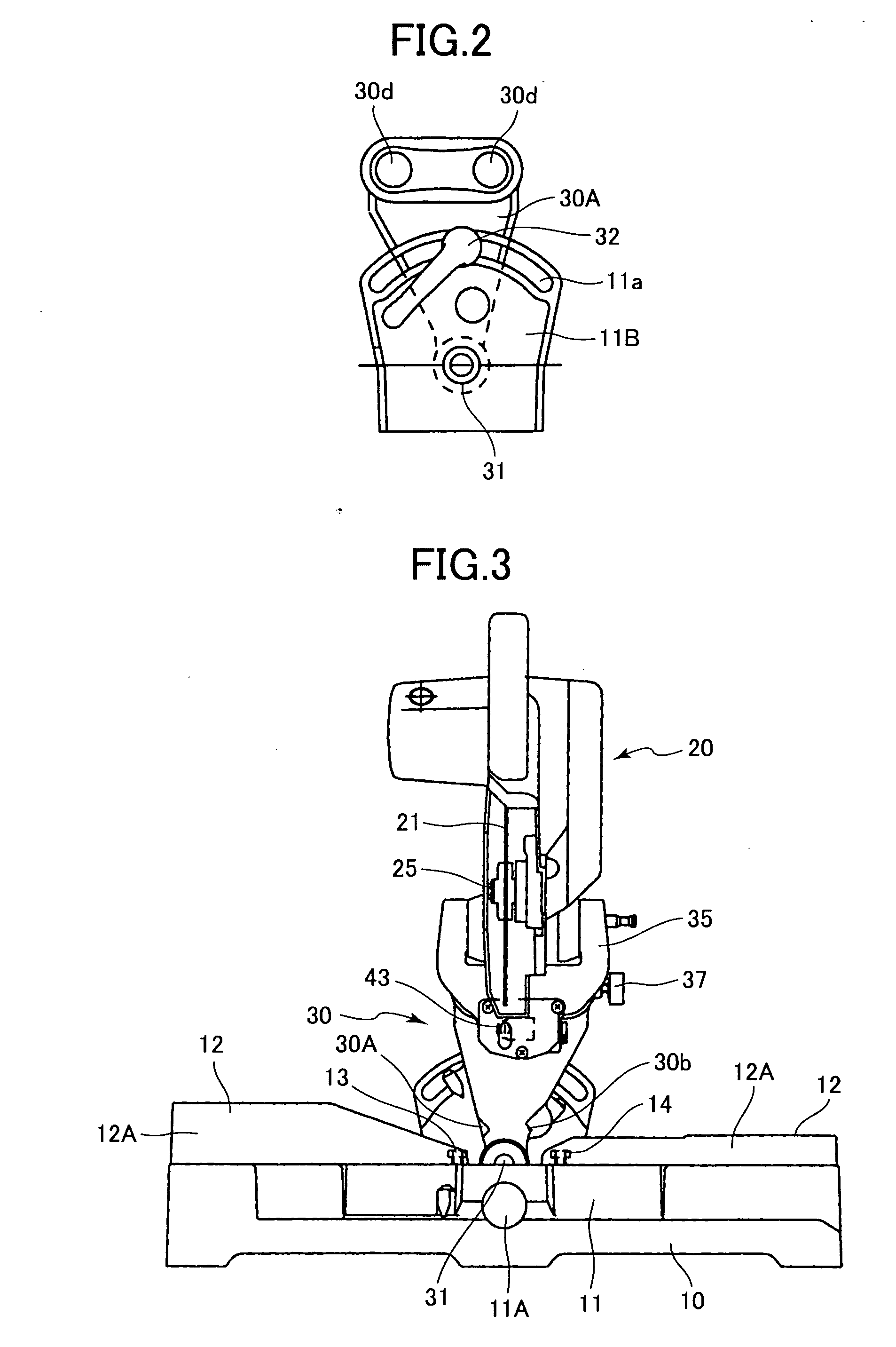
[0031] A miter saw according to the invention will be described with reference to FIG. 1 to FIG. 14. As shown in FIG. 1, the miter saw 1 includes a base 10, a turntable 11, a cutting unit 20, and a support section 30. The turntable 11 is supported on the base 10 and is rotatable about its axis with respect to the base 10. The cutting unit 20 holds a circular saw blade 21. The support section 30 stands upright from the rear portion of the turntable 11 to be pivotally movable. The support section 30 supports the cutting unit 20 movable toward and away from the turntable 11.

[0032] The turntable 11 is fitted, at its center part, in the base 10 and is angularly rotatable in a horizontal plane. The upper surface of the turntable 11 is substantially flush with the upper surface of the base 10. A workpiece W such as a wood block is placed on the upper surfaces of the base 10 and turntable 11. A pair of fences 12 are secured to the upper surface of the base 10 and extend across the turntable...

second embodiment

[0066] Next, a miter saw according to the invention will be described with reference to FIG. 15 to FIG. 17. As shown in FIG. 15, the miter saw 101 includes a base 110, a turntable 111, a cutting unit 120, and a support section 130. The turntable 111 is supported on the base 110 and is rotatable about its axis with respect to the base 110. The cutting unit 120 rotatably supports a circular saw blade 121. The support section 130 stands upright from the rear portion of the turntable 111 to be pivotally movable. The support section 130 supports the cutting unit 120 movable toward and away from the turntable 111.

[0067] The turntable 111 is fitted, at its center part, with the center potion of the base 110 and is angularly rotatable in a horizontal plane. The upper surface of the turntable 111 is substantially flush with the upper surface of the base 110. A workpiece W such as a wood block is placed on the upper surfaces of the base 110 and turntable 111. A pair of fences 112 are secured ...


PUM

PropertyMeasurementUnit
Thicknessaaaaaaaaaa
Coloraaaaaaaaaa

Abstract

A miter saw having first and second laser oscillators. A base is provided for mounting a worpiece. A fence extends in a lateral direction and is fixed to the base and has a front surface to which the workpiece is to be abutted. A cutting unit rotatably supports a circular saw blade. A support section is supported on the base and is pivotably supports the cutting unit movable toward and away from the base. The first laser oscillator is provided at the base for irradiating a first laser beam to the front side of the workpiece. The second laser oscillator is provided at the support section for irradiating a second laser beam to a rear side of the workpiece.

Description

BACKGROUND OF THE INVENTION [0001] The present invention relates to a miter saw, and more particularly, to the miter saw having two laser oscillators. [0002] For cutting a workpice by a miter saw, a marking line indicative of a cutting line is provisionally drawn on a surface of the workpiece, and a cutting is performed along the marking line. However, the marking line may be covered with cutting chips and becomes invisible, to degrade cutting efficiency. [0003] In order to avoid this problem, Japanese Patent Application Publication No. 2000-225603 discloses a miter saw provided with a laser oscillator which irradiates a laser beam so that the cutting can be performed along a laser beam projection line on an upper surface of a workpiece. [0004] The laser beam projection line can be easily recognized if the upper surface of the workpiece is flat. However, if the upper surface contains convex or concave regions, or wavy form such as a molding segment, the laser beam may generate a sha...

Claims


Application Information

Patent Timeline
IPC IPC(8): B26D5/08
CPCB23D59/003Y10T83/8773
Inventor USHIWATA, SHIGEHARUHORIUCHI, TAKAMOTO
Owner HITACHI KOKI CO LTD
Why Eureka
Try Eureka