Light emitting device

A light-emitting device and light-emitting surface technology, applied in mechanical equipment, lighting and heating equipment, optics, etc., can solve the problems of expensive, clear projection images, etc., and achieve the effect of simple structure and assembly

Pending Publication Date: 2021-12-31
SIGNIFY HLDG BV
View PDF1 Cites 0 Cited by
  • Summary
  • Abstract
  • Description
  • Claims
  • Application Information

AI Technical Summary

Problems solved by technology

However, the device is an omnidirectional light source for decorative lighting and is not capable of projecting clear images
[0005] Also, all known ideas for remotely adjusting beams are either expensive or require a lot of effort to construct and maintain for a reasonably long lifetime (say more than 50000 hours)

Method used


Image

  • Light emitting device
  • Light emitting device
  • Light emitting device

Examples


Embodiment Construction

[0066] The invention will now be described more fully hereinafter with reference to the accompanying drawings, in which presently preferred embodiments of the invention are shown. This invention may, however, be embodied in many different forms and should not be construed as limited to the embodiments set forth herein; rather, these embodiments are provided for thoroughness and completeness, and to fully convey the scope of the invention to those skilled in the art. .

[0067] figure 1 A cross-sectional side view of a lighting device 1 according to a first embodiment of the invention is shown.

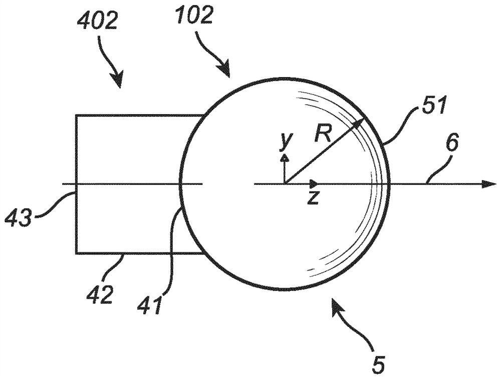
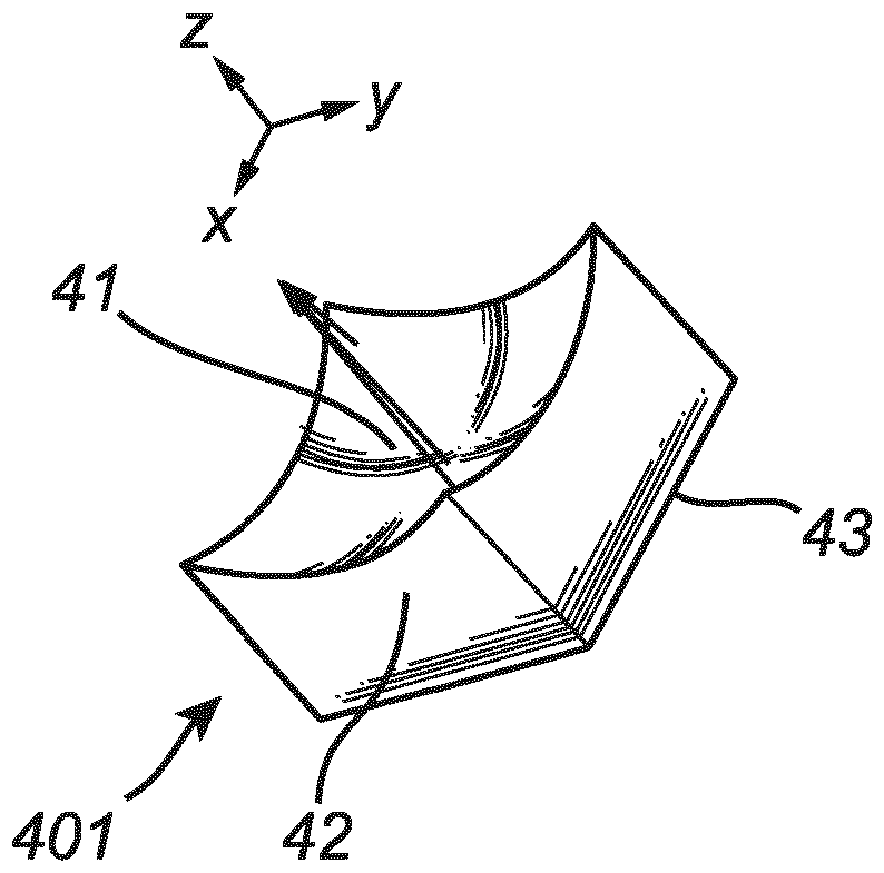
[0068] In general, and regardless of the embodiment, the light emitting device 1 is of a type suitable for projecting the light beam 15 onto a target surface. The lighting device 1 comprises at least one light engine 2 . The light engine 2 includes one or more light sources 3 , at least one light mixing chamber 4 and an optical assembly 5 . The optical assembly 5 has a spherical sh...


PUM

PropertyMeasurementUnit
sizeaaaaaaaaaa

Abstract

A light emitting device (1) adapted for projecting a light beam (15) onto a target surface, the light emitting device (1) comprising a light engine (2) comprising a light source (3), a light mixing chamber (4), and an optical component (5) having a spherical shape with a curved light-receiving surface (51), where the light source (3) is arranged to, in operation, emit light towards a light exit window (41) of the at least one light mixing 5 chamber, the light exit window (41) of the at least one light mixing chamber (4) thereby acting as an extended light source with a curved light-emitting surface, where the optical component (5) is provided adjacent to the light exit window (41) of the light mixing chamber, and wherein the curved light emitting surface of the at least one light mixing chamber (4) is conformal to an the curved light-receiving surface (51) of the optical component (5) and 10 coincident with a focal surface (52) of the optical component (5).

Description

technical field [0001] The present invention relates to a lighting device adapted to project a beam of light onto a target surface, the lighting device comprising at least one light engine comprising at least one light source adapted to emit light in operation, at least one light mixing chamber and an optical components. [0002] As used herein, a light mixing chamber is intended to mean a chamber, cavity, tube, or box, etc., which is adapted or capable of mixing light originating from one or more light sources and propagating therethrough to form an output which is The mixing of light from one or more light sources. Background technique [0003] Interest in dynamic LED lighting systems is rapidly increasing, in which the light beam changes its shape depending on the needs of the user. The beam can be controlled via a smartphone or a remote control. Current examples of beam steering use liquid crystal (LC) elements to control the shape of a collimated LED beam. Other exa...

Claims


Application Information

Patent Timeline
Patent Type & Authority Applications(China)
IPC IPC(8): F21V5/04F21V7/00F21K9/62F21V8/00G02B27/09F21V13/04F21Y115/10F21Y105/10
CPCF21V5/041F21V7/0033F21V13/04F21K9/62F21Y2115/10F21Y2105/10G02B27/0994G02B19/0066G02B19/0028G02B7/027
Inventor E·P·布尼坎普L·J·L·海宁J·J·瑞恩
Owner SIGNIFY HLDG BV
Why Eureka
Try Eureka