Implant for correction of spinal deformity

a technology for spinal degeneration and implants, which is applied in the field of devices for treating spinal disorders, can solve the problems of disc above and below the fusion zone in jeopardy of degeneration, invasive surgery, and excessive blood loss

Active Publication Date: 2006-03-02
GLOBUS MEDICAL INC
View PDF20 Cites 296 Cited by
  • Summary
  • Abstract
  • Description
  • Claims
  • Application Information

AI Technical Summary

Benefits of technology

[0009] In one aspect, the present invention relates to a device for correction of a spinal deformity. In one embodiment, the device includes a cable having a first end portion, and an opposite, second end portion, and a tension member having a cylindrical magnet, a leadscrew and a body. In one embodiment, the leadscrew has a helically threaded exterior surface, an interior surface defining a bore for housing the cylindrical magnet rigidly, an axis therethrough the bore, a first end and an opposite, second end, and a length, L2, defined therebetween. The body has a first end portion and an opposite, second end portion defining a cylindrical chamber therebetween, a longitudinal axis therethrough the cylindrical chamber, a U-shape cut formed in the first end portion, and a length, L1, defined therebtween the first end portion and the second end portion, where L1>L2. In one embodiment, the cylindrical chamber has a first chamber portion and a second chamber portion neighboring to the first chamber portion. The first chamber portion and the second chamber portion are sized with a diameter, d1, and d2, respectively, where d2>d1 such that a step is formed at the junction of the first chamber portion and the second chamber portion. The first chamber portion is helically threaded for engaging with the leadscrew such that when the leadscrew is received in the cylindrical chamber, the axis of the leadscrew is substantially coincident with the longitudinal axis of the body and the leadscrew is capable of moving back and forth along the longitudinal axis as being rotated around the longitudinal axis. In one embodiment, the tension member further has a first cap and a second cap attached to the first end and the second end of the leadscrew, respectively. The second cap is sized to fit the second chamber portion of the cylindrical chamber such that as assembled, the second cap prevents the leadscrew from moving out of the cylindrical chamber of the body of the tension member.
[0011] Moreover, the device includes a first engaging member mechanically engaging the first end portion of the cable with the tension member. In one embodiment, the first engaging member includes a ball-and-socket joint mechanism. The first engaging member has a swaged ball attached to the first end portion of the cable, and a pivot cap having a shoulder and a hole formed on the shoulder. As assembled, the first end portion of the cable is received through the hole of the pivot cap and the pivot cap is attached to the first end cap of the tension member such that the swaged ball articulates with the shoulder of the pivot cap, and thus rotating the leadscrew around its axis does not cause the cable to rotate and twist.
[0015] In one embodiment, the cable is made of a biocompatible material. The biocompatible material includes a polymer, a composite, a metal, an alloy, or any combination thereof. In one embodiment, the cable is coated with a material to reduce abrasion and adhesion of biologic tissues.
[0018] In one embodiment, the first engaging member includes a ball-and-socket joint mechanism. The first engaging member has a swaged ball attached to the first end portion of the cable, and a pivot cap having a shoulder and a hole formed on the shoulder. As assembled, the first end portion of the cable is received through the hole of the pivot cap and the pivot cap is attached to the head of the leadscrew of the tension member such that the swaged ball articulates with the shoulder of the pivot cap, and thus rotating the leadscrew around its axis does not cause the cable to rotate and twist. In another embodiment, the first end portion of the cable is formed with a loop portion, and the first engaging member has a pin, and a crimp. As assembled, the loop portion of the first end portion of the cable engages with the pin and is secured with the crimp.

Problems solved by technology

It is believed that the surgery is arduous, invasive, and has an array of potential complications including excessive blood loss.
The discs above and below the fusion zone are in jeopardy of degeneration due to the increased biomechanical demands placed on them.
Also, flat back syndrome could be problematic if normal lordosis and kyphosis are not restored.
Recovery could be a lengthy and painful process.
Even a successful procedure rarely results in a normal spinal curvature and the patient is left with an immobile spinal section.
A flaw in the conventional implants for correction of the spinal curvature deformity is that the implants are usually of a part of the load path of the spinal column.
Spinal loads could be large, and the geometry of the implants used is such that they may not support such large loads indefinitely.
Fatigue failure of the implant occurs if fusion is delayed.
A further disadvantage of the conventional implants for correction of the spinal curvature deformity is the potential for neurologic damage.
Even after the surgery, the spinal loads could be large enough to cause nerve damages.
However, stiff instrumentation provides negligible additional correction even though resistive forces in the spine are decreasing.
Therefore, a heretofore unaddressed need exists in the art to address the aforementioned deficiencies and inadequacies.

Method used


Image

  • Implant for correction of spinal deformity
  • Implant for correction of spinal deformity
  • Implant for correction of spinal deformity

Examples


Embodiment Construction

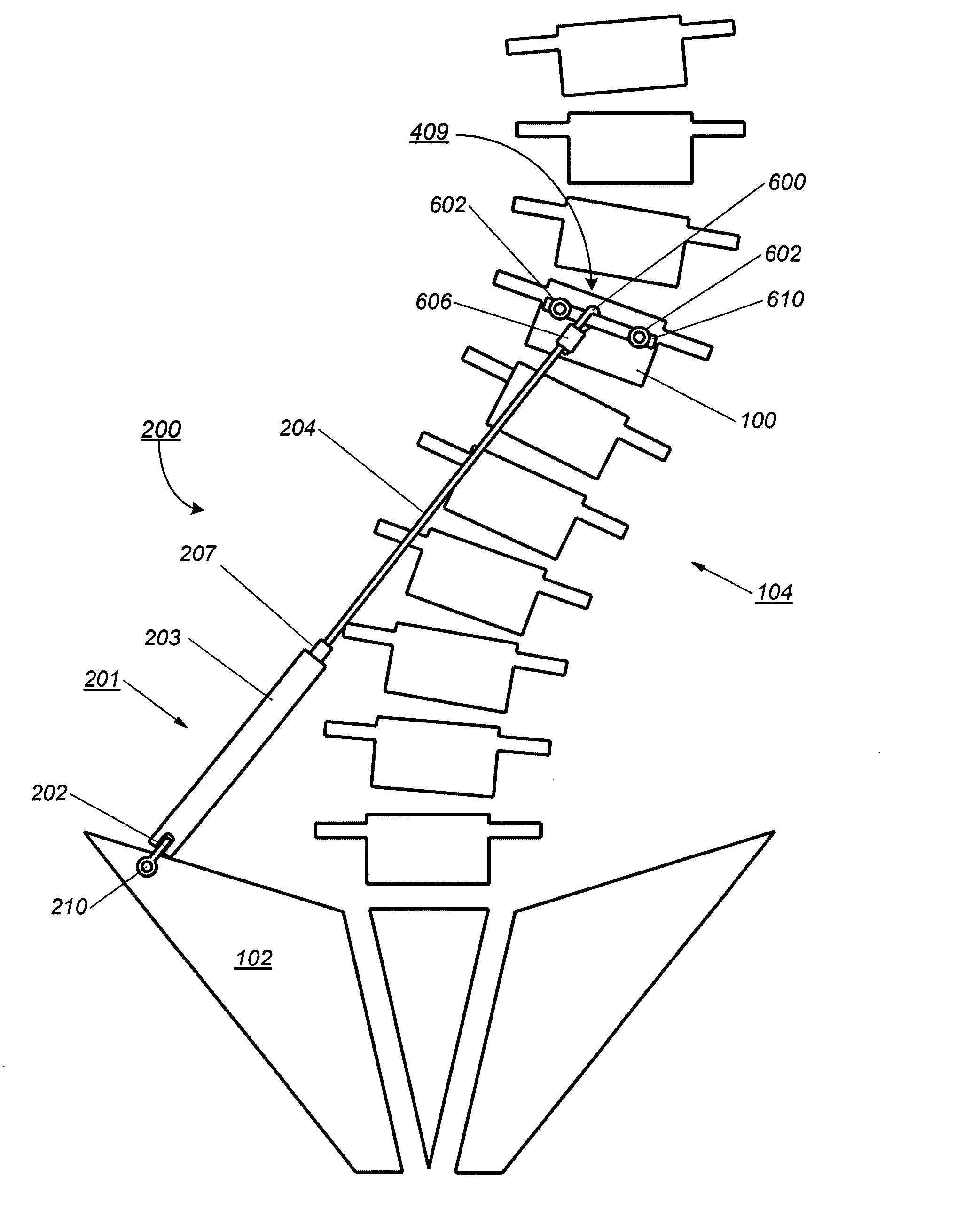
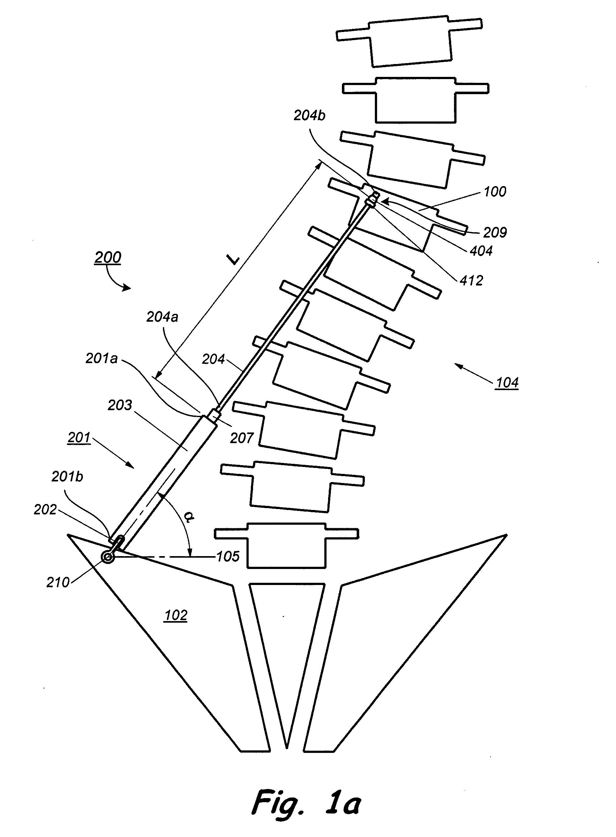
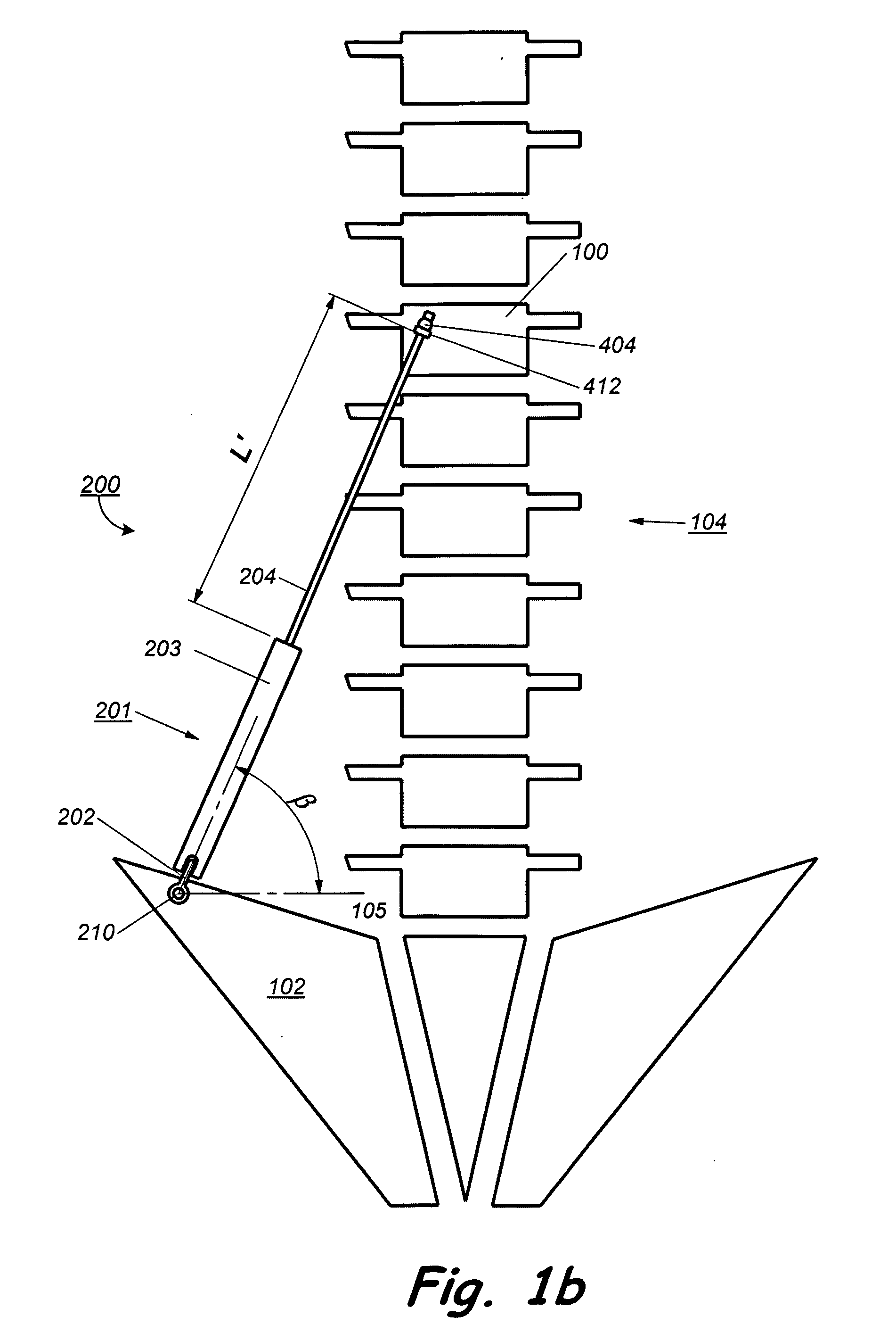
[0041] The present invention is more particularly described in the following examples that are intended as illustrative only since numerous modifications and variations therein will be apparent to those skilled in the art. Various embodiments of the invention are now described in detail. Referring to the drawings, like numbers indicate like parts throughout the views. As used in the description herein and throughout the claims that follow, the meaning of “a,”“an,” and “the” includes plural reference unless the context clearly dictates otherwise. Also, as used in the description herein and throughout the claims that follow, the meaning of “in” includes “in” and “on” unless the context clearly dictates otherwise.

[0042] The description will be made as to the embodiments of the present invention in conjunction with the accompanying drawings 1-16. In accordance with the purposes of this invention, as embodied and broadly described herein, this invention, in one aspect, relates to an imp...


PUM


Abstract

A device for correction of a spinal deformity. In one embodiment, the device includes a cable having a first end portion, and an opposite, second end portion attachable to a vertebra, and means for adjusting the tension of the cable so as to impose a corrective displacement on the vertebra.

Description

CROSS-REFERENCE TO RELATED PATENT APPLICATION [0001] This application claims priority to and the benefit of, pursuant to 35 U.S.C. § 119(e), U.S. provisional patent application Ser. No. 60 / 605,548, filed Aug. 30, 2004, entitled “Implant For Correction Of Spinal Deformity,” by Jeffrey D. Gordon, which is incorporated herein by reference in its entirety.FIELD OF THE INVENTION [0002] The present invention generally relates to a device for treatment of spine disorders, and in particular to the utilization of an implant to impose a corrective displacement on a vertebra of a patient so as to incrementally correct abnormal spinal curvature(s) of the patient. BACKGROUND OF THE INVENTION [0003] Scoliosis is a spinal deformity that has an abnormal lateral curvature of the spine when viewed from a posterior perspective. The abnormal curvature of the spine is commonly associated with abnormal spinal rotation causing ribs to protrude posteriorly into what is commonly referred to as “rib hump”. T...

Claims


Application Information

Patent Timeline
Patent Type & Authority Applications(United States)
IPC IPC(8): A61F2/30
CPCA61B17/7016A61B17/7022A61B17/7055A61B17/7053
Inventor GORDON, JEFFREY D.
Owner GLOBUS MEDICAL INC
Why Eureka
Try Eureka