Advanced sleep timer

a technology of sleep timer and timer, which is applied in the field of sleep timer, can solve the problem that the operation does not reflect the individual situation of the user

Inactive Publication Date: 2006-03-09
HARMAN BECKER AUTOMOTIVE SYST
View PDF1 Cites 45 Cited by
  • Summary
  • Abstract
  • Description
  • Claims
  • Application Information

AI Technical Summary

Problems solved by technology

While these sleep timers use different ways to switch off the device, their operation does not reflect the indi

Method used


Image

  • Advanced sleep timer
  • Advanced sleep timer
  • Advanced sleep timer

Examples


Embodiment Construction

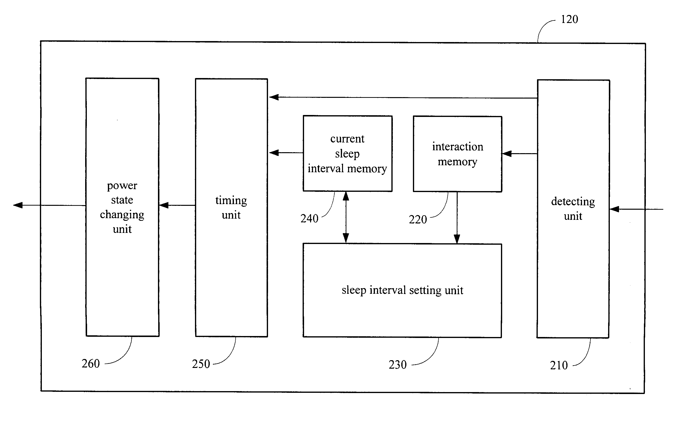
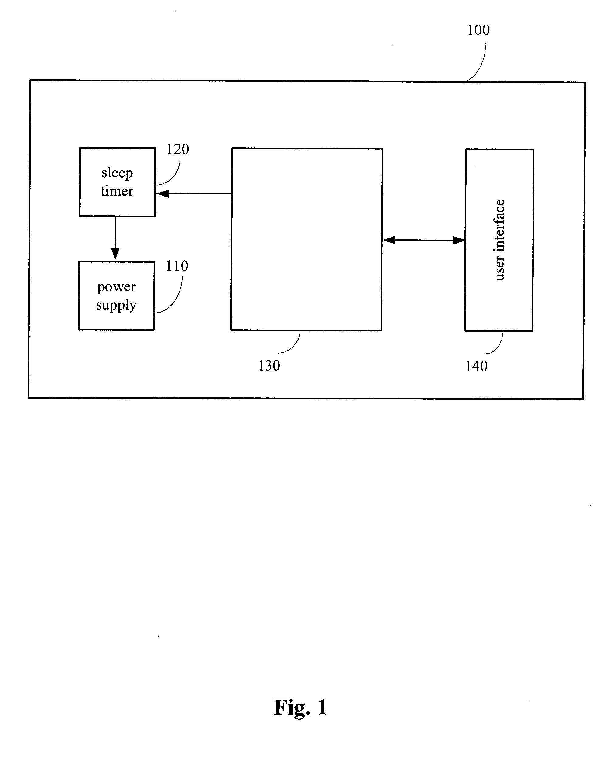
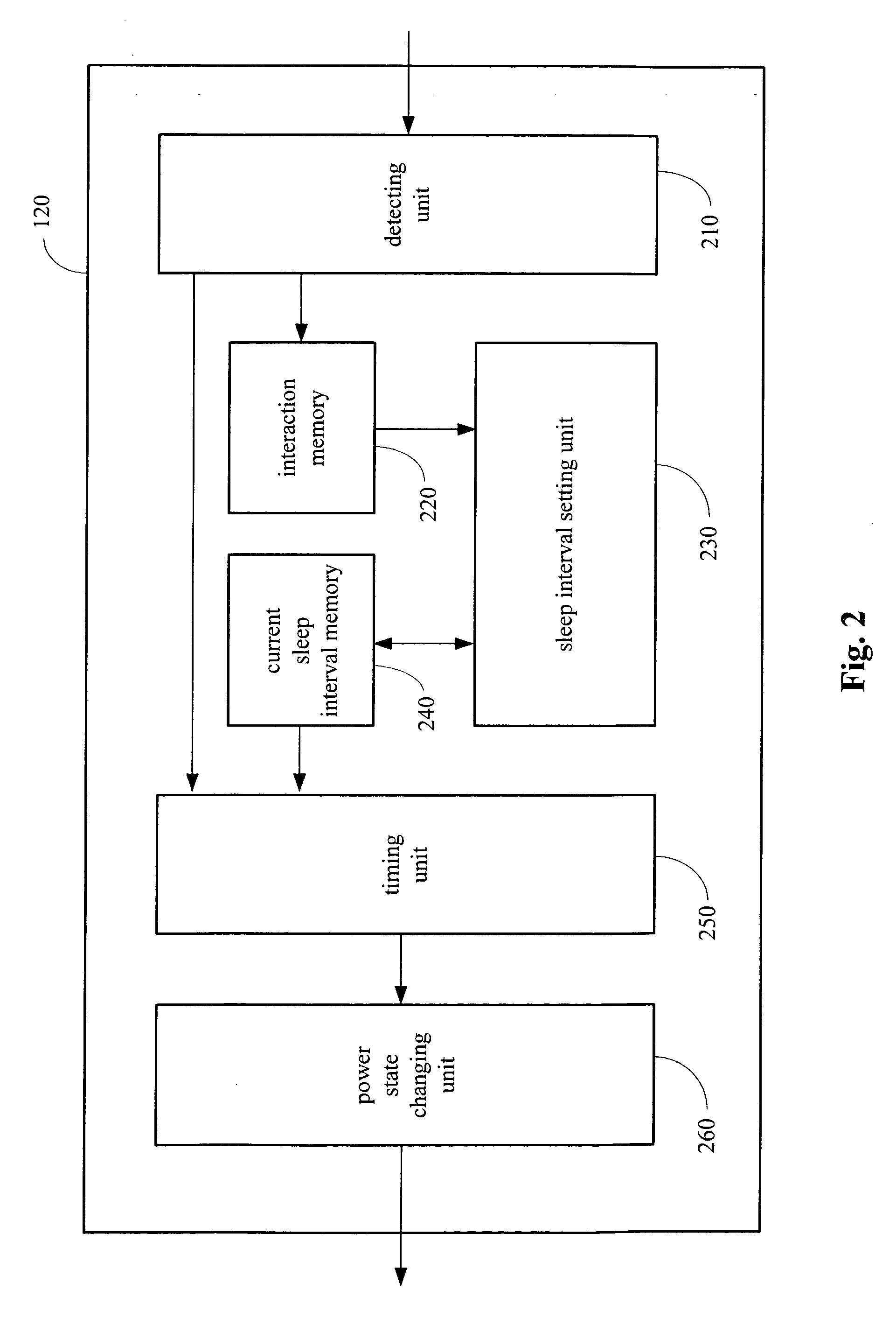
[0025] A sleep timer may consider a user's profile of interaction with a controlled device when determining a power state changing time. User interactions may be monitored to create the user's profile of interaction. User interactions may include pressing a key on the controlled device, a remote control, or on another device. Many or all interactions of the user with the controlled device may be considered to represent a kind of keep alive message.

[0026] By performing statistical evaluations based on user interaction data, a sleep timer may determine a user's behavioural characteristics. Some user behavioural characteristics may include the minimal, the average, and / or the maximum time interval between two subsequent user interactions. The sleep interval, the time elapsed before a power state change is initiated, may be determined based on at least one of these calculated values. A power state change may include transitioning a controlled device from an active state to a standby mo...


PUM


Abstract

A sleep timer for changing a power state of a device includes a detector, a memory, a sleep interval setting unit, a timer, and a power unit. The detector detects interactions between a user and an active device. The memory is linked to the detector and stores the historical user interaction data. Based on the historical user interaction data, the sleep interval setting unit adjusts the sleep timer's sleep interval. The timer determines a power changing point in time based on the sleep interval. At the power state changing point in time, the power unit initiates a power state change.

Description

PRIORITY CLAIM [0001] This application claims the benefit of priority from European Patent Application No. 04016481.6, filed Jul. 13, 2004, which is incorporated herein by reference.BACKGROUND OF THE INVENTION [0002] 1. Technical Field [0003] This invention relates to a sleep timer for controlling the power state of a device, and more particularly to a module for automatically changing the power state of a variety of devices at a predetermined point in time. [0004] 2. Related Art [0005] Audio / visual recording devices may be equipped with a sleep timer. A sleep timer may be a module that is used to power off a device or to set a device into a standby mode at a predetermined point in time. The point in time is set such that a user has most likely finished using the device, such as when the user has fallen asleep. In this way, power consumption can be reduced, saving battery capacity. [0006] Some sleep timers are manually activated by the user by selecting a time interval from a predef...

Claims


Application Information

Patent Timeline
IPC IPC(8): G06F1/26
CPCG06F1/3203G06F1/3246G11B19/06H04N5/63H04N1/00891H04N1/00928H04N1/00885
Inventor MENZL, THOMAS
Owner HARMAN BECKER AUTOMOTIVE SYST
Why Eureka
Try Eureka