Optical disc recording device

Inactive Publication Date: 2006-03-09
LITE ON IT
View PDF13 Cites 8 Cited by
  • Summary
  • Abstract
  • Description
  • Claims
  • Application Information

AI Technical Summary

Benefits of technology

[0011] Accordingly, the present invention provides an optical disc recording device capable of stabilizing the inner flow field of the optical disc recording device and effectively increasing the writing quality.
[0019] Based on the description above, in the present invention, a first protrusion and a second protrusion are disposed in proper locations on the top cover of the optical disc recording device such that the inner flow field of the optical disc recording device can be stabilized and the writing quality using the optical discs recording device can be enhanced.

Problems solved by technology

Generally speaking, users could access the data recorded on the optical discs by using read-only memory (CD-ROM), which however, is unable to record the data on the optical discs.
When the optical disc recording device 100 is writing data on the disc at 32× speed in location about 44th to 48th minute (at a rotation speed about 7600 rounds per minute), due to the unstable flow field in the optical disc recording device caused by the high-speed rotation of the optical disc, and the coupling effect between the unstable flow field and the optical disc, the optical disc would thus flutter or deform, which not only lowers the writing quality but also results in failure in writing / accessing data in location about the 44th to the 48th minute.
However, if the error rate C1 of decoding output of the RS-code in the first layer and the error rate C2 of decoding output of the RS-code in the second layer are too high, it means the writing quality deteriorates, which results in failing in writing / accessing data in the location about 44th to 48th minutes.

Method used


Image

  • Optical disc recording device
  • Optical disc recording device
  • Optical disc recording device

Examples


Embodiment Construction

[0031] In this embodiment, the 32× optical disc recording device is used as an example in the following, but the present invention is not limited thereto.

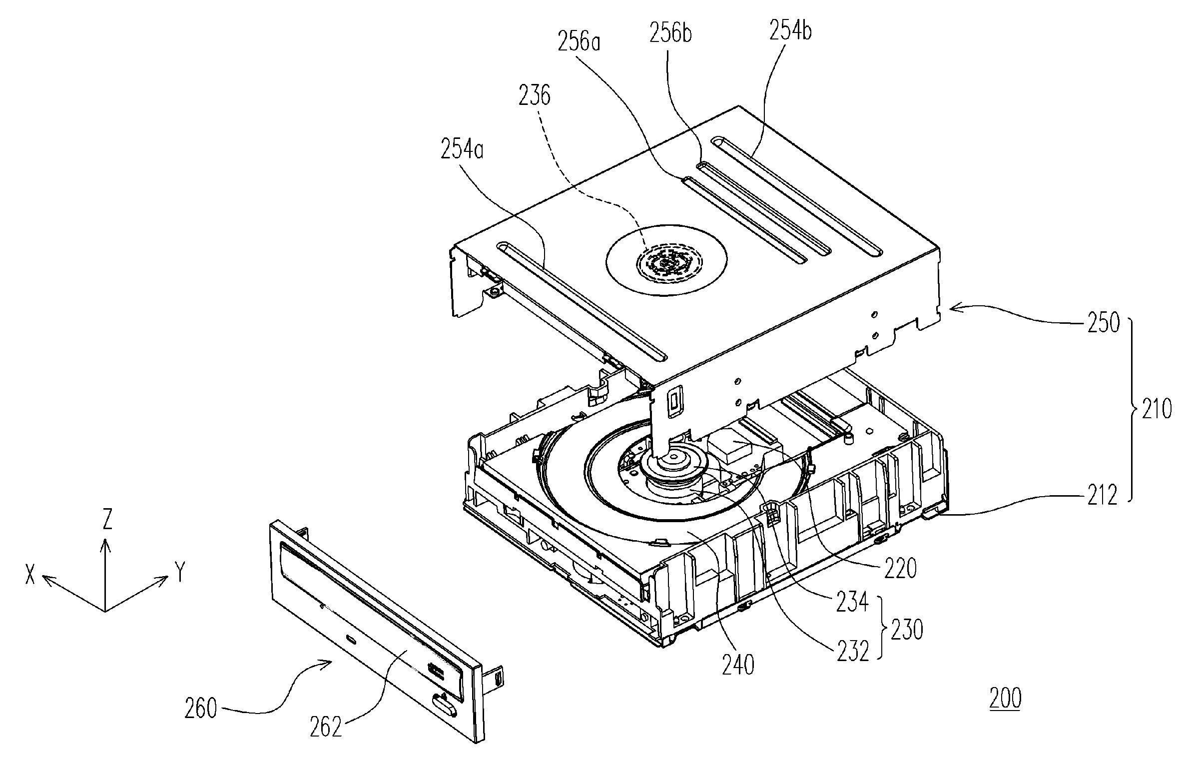
[0032]FIG. 2A is shows a schematic and exploded diagram of an optical disc recording device according to an embodiment of the present invention. And FIG. 2B schematically illustrates the structure of an optical write / read module and a transmission module of the optical disc recording device according to an embodiment of the invention. Please refer to FIG. 2A and FIG. 2B, the optical disc recording device 200 comprises a housing 210, an optical write / read module 220, and a transmission module 230. The housing 210 comprises a bottom housing 212 and a top cover 250. The optical write / read module 220 and the transmission module 230 are disposed inside the housing 210 respectively.

[0033] As mentioned, the optical disc recording device 200, for example, further comprises a front plate 260 connected to the top cover 250 and bottom housi...


PUM


Abstract

An optical disc recording device including a housing, an optical read / write module and a transmission module. Both the optical read / write module and the transmission module are disposed inside the housing. Besides, the housing includes a bottom housing and a top cover. The inner surface of top cover has a first protrusion and a second protrusion, which together can stabilize the flow-field in the optical disc recording device so that the optical disc can rotate stably.

Description

CROSS-REFERENCE TO RELATED APPLICATION [0001] This application claims the priority benefit of Taiwan application serial no. 93127121, filed on Sep. 8, 2004. BACKGROUND OF THE INVENTION [0002] 1. Field of Invention [0003] The present invention relates to an optical disc recording device. More particularly, the present invention relates to an optical disc recording device capable of stabilizing inner flow field. [0004] 2. Description of Related Art [0005] The optical discs have such advantages as large storage capacity, easy preservation, long preservation period, low cost, and so on. Consequently, the optical discs now have gradually replaced traditional magnetic storing medium as one of indispensable optical storing media for modern people. Generally speaking, users could access the data recorded on the optical discs by using read-only memory (CD-ROM), which however, is unable to record the data on the optical discs. Thus, the CD recording device having both reading and recording fu...

Claims


Application Information

Patent Timeline
IPC IPC(8): G11B7/24G11B33/14
CPCG11B17/0285G11B33/121G11B33/08
Inventor HSIEH, CHIH-CHUNGCHEN, JENG-JIUNCHEN, BOR-RUEYLEU, HUI-CHUNG
Owner LITE ON IT
Why Eureka
Try Eureka