Optical scanning apparatus

a scanning apparatus and optical technology, applied in the direction of magnification glasses, instruments, mountings, etc., can solve the problems of difficult to change the focal position of a light beam at high speed, low response speed, and difficult to say that this method can be suitably applied to a high-speed device such as a laser printer

Inactive Publication Date: 2009-10-13
CANON KK
View PDF7 Cites 2 Cited by
  • Summary
  • Abstract
  • Description
  • Claims
  • Application Information

AI Technical Summary

Benefits of technology

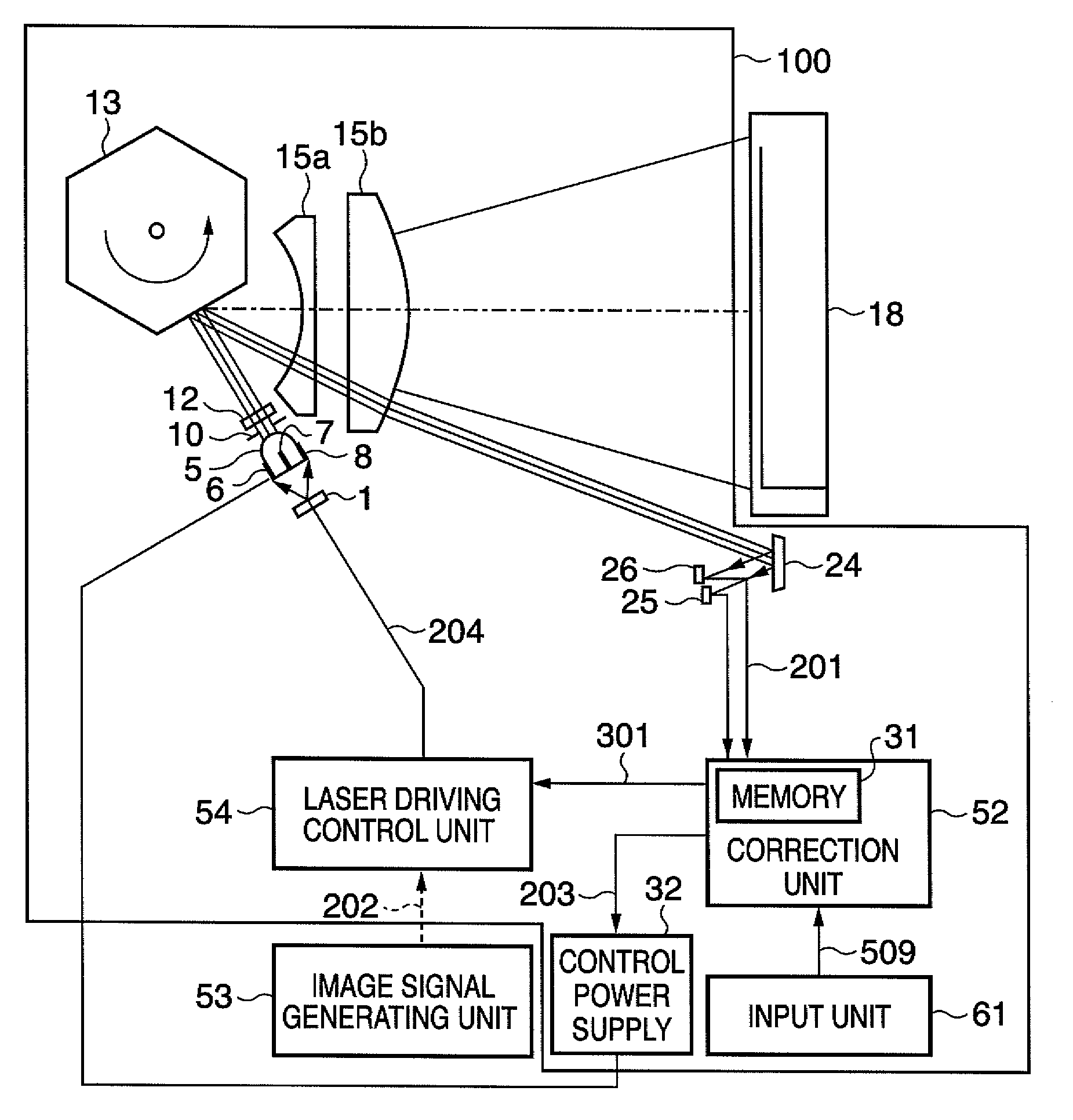
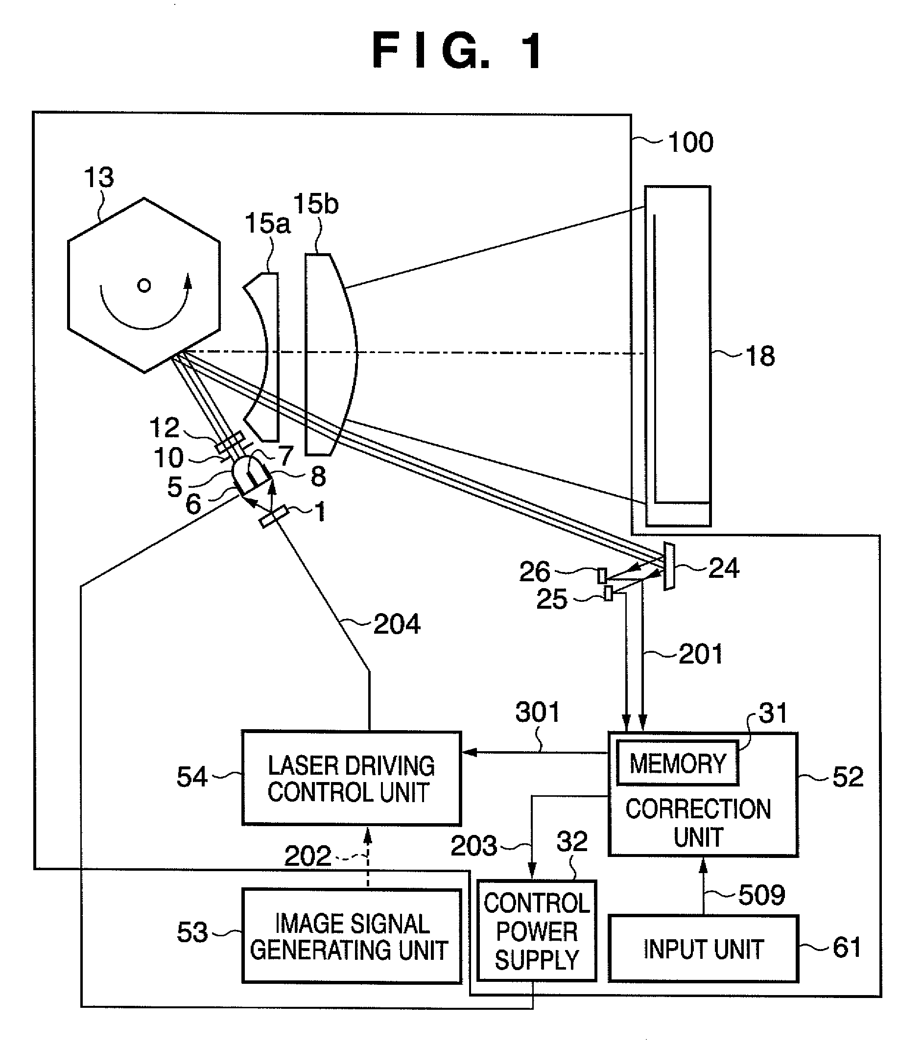
[0011]The present invention has been made in consideration of the above prior art, and has as its object to provide a compact optical scanning apparatus which can change the focal position of a light beam at high speed with a small number of components.
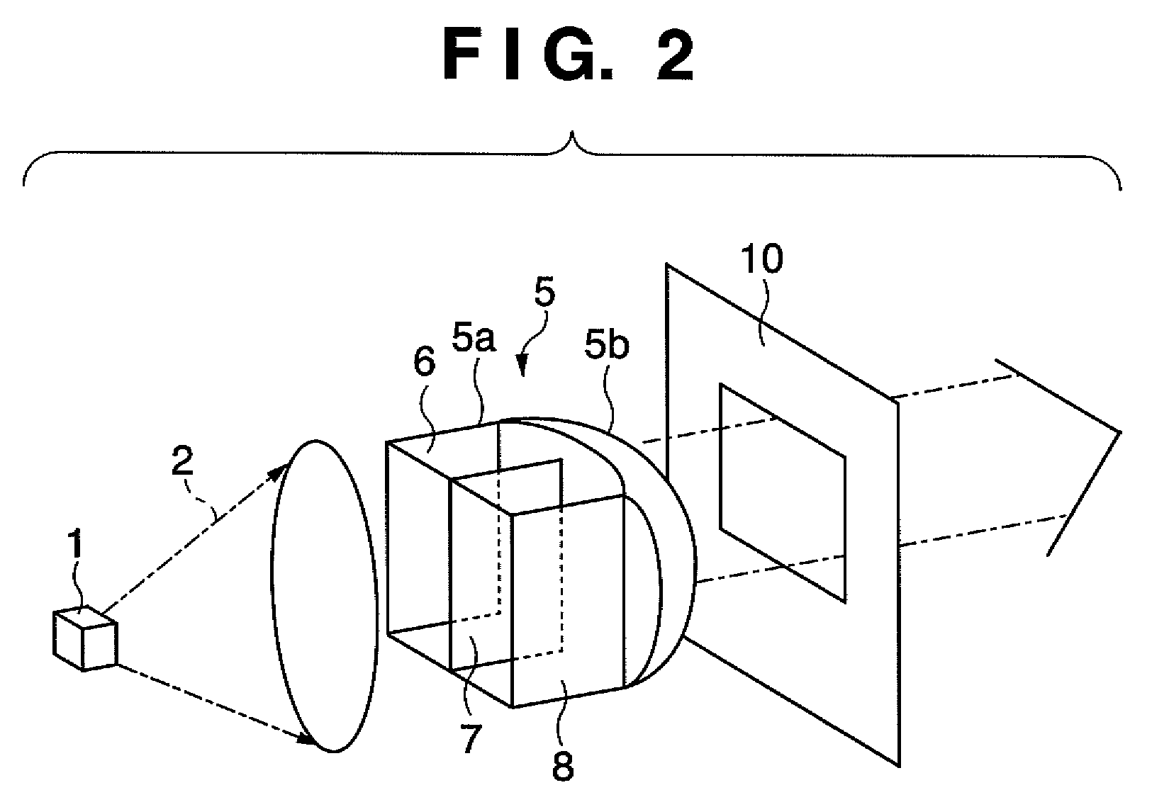
[0013]According to the present invention, it is possible to quickly change the focusing characteristic of a light beam transmitted through the collimating lens or the cylindrical lens formed by an electro-optics crystal between the respective electrodes placed inside and outside the lens by applying a voltage to each electrode. This makes it possible to quickly displace the focal position of a light beam to be deflected / scanned, thereby improving the accuracy of the focal position of a light beam in the entire scanning range. As a result, the write quality on the surface of the photosensitive member to be scanned or the like can be improved.
[0014]In addition, since the collimating lens itself is formed by an electro-optics crystal, there is no need to add any new components as in the prior art. This can decrease the number of components required and reduce the size and cost of the apparatus.

Problems solved by technology

In addition, the response speed is low because of mechanical movement, and hence it is difficult to change the focal position of a light beam at high speed.
For this reason, it is hard to say that this method can be suitably applied to a high-speed device such as a laser printer.
As a result, the number of required components increases, and the optical scanning apparatus increases in size.
These causes make it difficult to improve the accuracy of the focal position of laser light in an entire scanning range in the main scanning direction.

Method used


Image

  • Optical scanning apparatus
  • Optical scanning apparatus
  • Optical scanning apparatus

Examples


second embodiment

[0067]An optical scanning apparatus according to the second embodiment of the present invention will be described next with reference to FIG. 6. Note that a repetitive description of the first embodiment will be omitted. The optical scanning apparatus according to the second embodiment of the present invention uses a cylindrical lens 27 in FIG. 6 instead of the cylindrical lens 12 in FIG. 1. In addition, unlike in the first embodiment described above, in the second embodiment, the cylindrical lens 27, instead of the collimating lens 5, is formed by a KTN crystal.

[0068]The cylindrical lens 27 has a quadratic prism-like main body 27a and a convex curve portion 27b placed on the distal end side of the main body 27a (on the optical aperture 10 side). Plate-like external electrodes 28a and 28c are placed on two opposing surfaces of the quadratic prism-like main body 27a of the cylindrical lens 27, and a plate-like internal electrode 28b is placed in the main body 27a to be parallel to th...


PUM


Abstract

A compact optical scanning apparatus which can change the focal position of a light beam at high speed is provided. In this optical scanning apparatus, a collimating lens (5) which parallelizes a light beam from a light source (1) is formed by a KTN crystal, and electrodes (7, 6, 8) are placed inside and outside the collimating lens (5).

Description

BACKGROUND OF THE INVENTION[0001]1. Field of the Invention[0002]The present invention relates to an optical scanning apparatus and, more particularly, to an optical scanning apparatus which is used for a recording engine unit in a laser printer or the like to form an image by scanning a photosensitive member with a light beam.[0003]2. Description of the Related Art[0004]An optical scanning apparatus in an electrophotographic image forming apparatus drives a semiconductor laser in accordance with input image data and forms an electrostatic latent image corresponding to the image data on a photosensitive member.[0005]A collimating lens converts laser light emitted from a semiconductor laser used as a light source for an optical scanning apparatus into almost parallel light, and a deflecting member such as a rotating polygon mirror deflects the light with a predetermined beam diameter. The light is then subjected to the focusing effect of an f-θ lens. At the same time, the f-θ lens cor...

Claims


Application Information

Patent Timeline
Patent Type & Authority Patents(United States)
IPC IPC(8): G02B27/30G02B3/00
CPCG02B1/02G02B7/008G02B26/128G02B27/0031G02B19/0014G02F1/29G02B19/0052G02B27/0938G02F2201/12G02F2203/28
Inventor MOGI, SHIN
Owner CANON KK
Why Eureka
Try Eureka