Bicycle shifter

a technology for shifting wheels and bicycles, applied in the direction of linear movement shafts, flexible shafts, shafts, etc., can solve the problem of not being able to adjust the lever reach for a variety of hand sizes of riders

Active Publication Date: 2006-03-16
SRAM
View PDF9 Cites 38 Cited by
  • Summary
  • Abstract
  • Description
  • Claims
  • Application Information

AI Technical Summary

Benefits of technology

[0003] The present invention provides a bicycle shifter with adjustable lever reach to accommodate varying hand sizes of individual riders. The bicycle shifter generally includes a shifter housing, a cable spool for pulling and releasing a control cable connected to a gear change device, cable pull and release lever mechanisms, and a clamp for mounting the shifter to the handlebar of the bicycle. The cable spool rotates about an axis. The cable release lever mechanism rotates the cable spool in a cable-release direction and includes a cable release lever. The cable pull lever mechanism rotates the cable spool in a cable-pull direction and includes a cable pull lever. Preferably, the cable pull lever is rotatable about the cable spool axis, the swept motion of the cable pull lever defining a first plane of motion substantially perpendicular to the cable spool axis. The cable release lever is rotatable about a cable release lever axis, the swept motion of the cable release lever defining a second plane of motion substantially perpendicular to the cable release lever axis. Preferably, the first and second planes of motion form an angle of approximately 60 degrees. The cable pull and release levers include contact surfaces configured to be operated by the thumb. The contact surface of the cable pull lever is shaped and sized differently than the contact surface of the cable release lever. The contact surface of the cable pull lever preferably faces toward a rearward direction, opposite the forward riding direction and is disposed behind the cable release lever. The contact surface of the cable release lever is preferably partially inclined to allow the thumb to slip along the inclined contact surface when the rider moves his thumb in the forward riding direction. Further, the lever contact surfaces are oriented and positioned such that when the rider grips a handgrip element on the handlebar, the rider's thumb readily reaches the contact surfaces.

Problems solved by technology

However, one disadvantage of this shifter is that lever reach is not adjustable for a variety of rider hand sizes.

Method used


Image

  • Bicycle shifter
  • Bicycle shifter
  • Bicycle shifter

Examples


Embodiment Construction

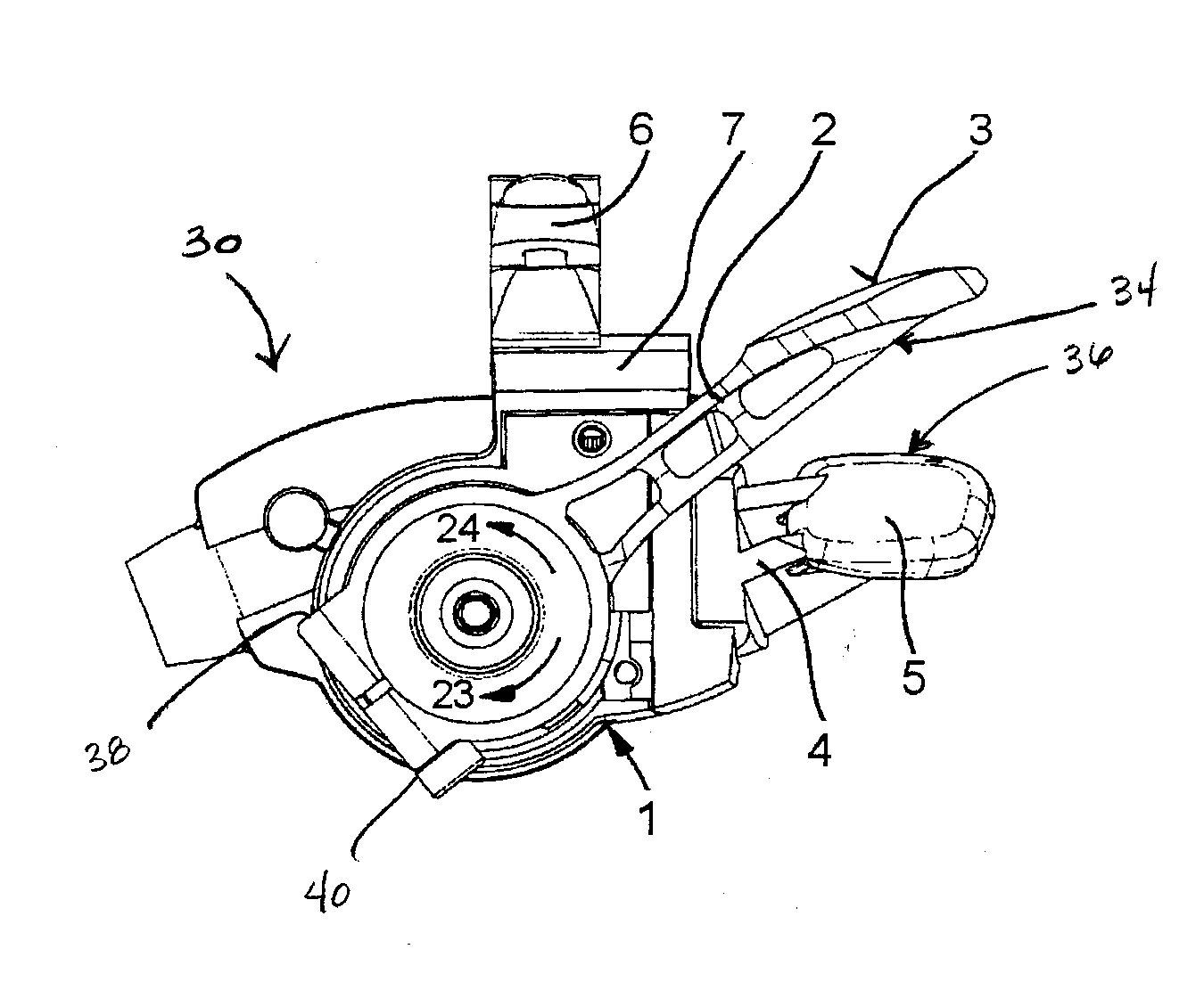
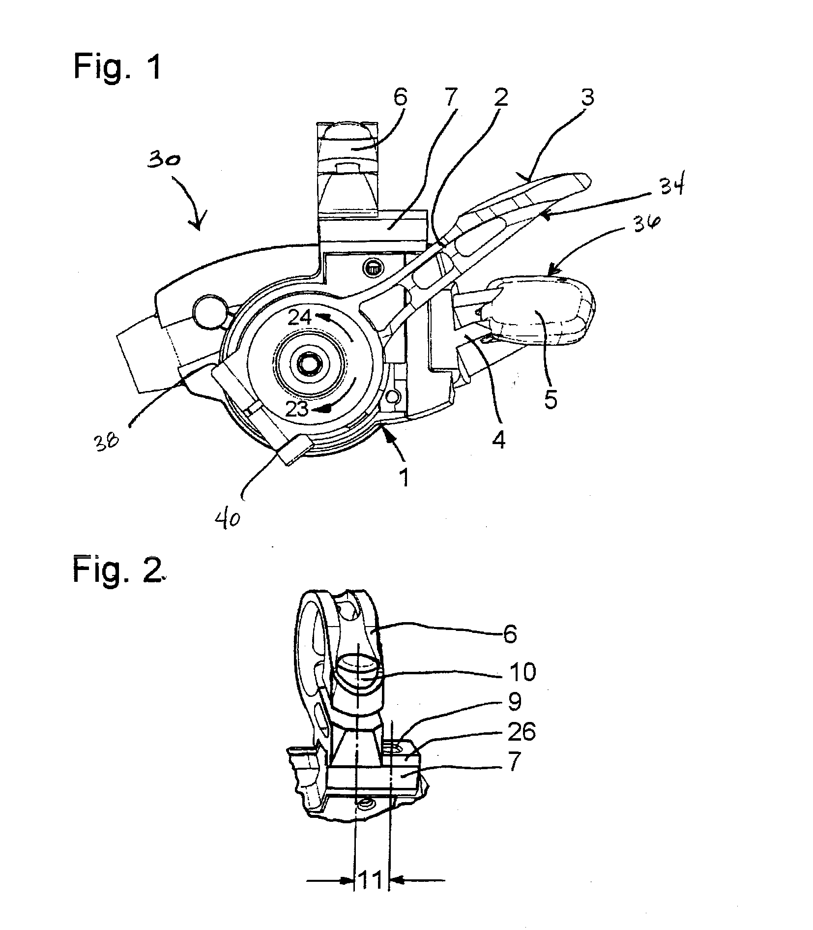
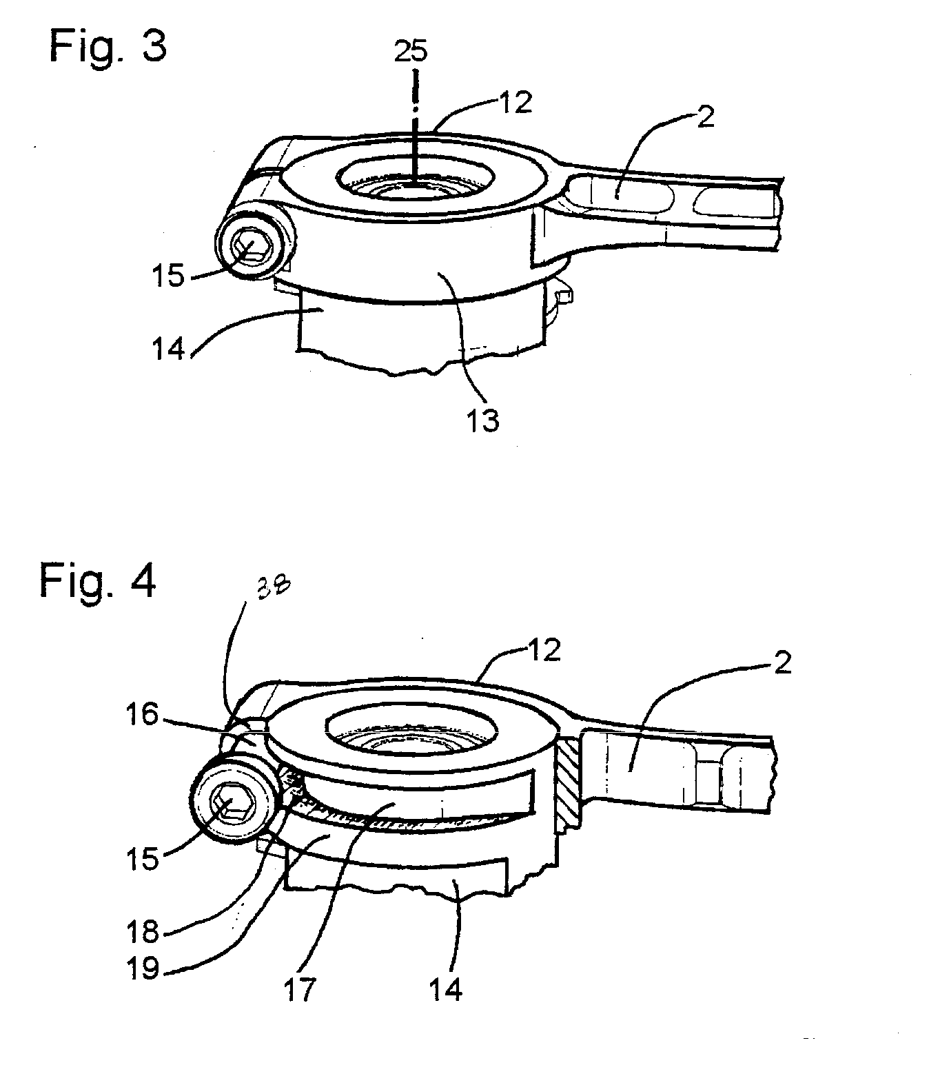
[0016]FIGS. 1-8 illustrate a bicycle shifter 30 according to one embodiment of the present invention. The shifter 30 generally includes a shifter housing 1, a cable spool 32, cable pull and release lever mechanisms 34, 36 and a clamp 6 for mounting the shifter 30 to a handlebar 8 of the bicycle. The cable spool 32 is rotatable about an axis 25 and has a cable groove for receiving a control cable. The cable groove may include a seat for securing an end of the control cable. The other end of the control cable is connected to a gear change device (not shown). The cable pull lever mechanism 34 rotates the cable spool 32 in the cable-pull or winding direction 23 to shift gears in a first direction, and the cable release lever mechanism 36 rotates the cable spool 32 in the cable-release or unwinding direction 24 to shift gears in a second direction.

[0017] Looking to FIG. 8, preferably, the cable pull lever mechanism 34 includes a cable pull lever 2 rotatable about the axis 25, the swept ...


PUM


Abstract

A bicycle shifter configured to be adjustable to accommodate a variety of sized hands. The shifter includes a housing, a cable spool for pulling and releasing a control cable, pull and cable release lever mechanisms and a clamp for mounting the shifter to a handlebar. The cable pull lever mechanism includes a cable pull lever and a driver element operatively connected to the cable spool. The release mechanism includes a cable release lever. The cable pull lever is attachable to the driver element at various orientations to vary the position of the cable pull lever relative to the cable release lever. The clamp is attachable to the shifter housing at different positions to vary the pull and cable release levers relative to the handgrip element on the handlebar.

Description

BACKGROUND OF THE INVENTION [0001] The present invention relates to bicycle shifters, and more particularly, to a bicycle shifter having a cable pull lever adjustable relative to a cable release lever and both levers adjustable relative to a handgrip element on a handlebar of the bicycle. [0002] European Patent No. 1 270 396 A2 discloses a bicycle shifter for actuating a gear change device. The shifter is mounted to a handlebar adjacent a brake lever mechanism. A cable pull lever of the shifter is generally in an ergonomic position relative to a handgrip element on the handlebar. However, one disadvantage of this shifter is that lever reach is not adjustable for a variety of rider hand sizes. A fastener that secures the shifter to the handlebar only allows the shifter, and in turn the cable pull lever, to be adjusted along and about the handlebar. Accordingly, there is a need for a bicycle shifter that accommodates a variety of riders. SUMMARY OF THE INVENTION [0003] The present inv...

Claims


Application Information

Patent Timeline
Patent Type & Authority Applications(United States)
IPC IPC(8): F16C1/10
CPCB62K19/30Y10T74/20438B62M25/04B62K23/06
Inventor MCLAUGHLIN, SCOTTWEISS, MARTINBOEHM, ROBERT
Owner SRAM
Why Eureka
Try Eureka