Method and device for triggering emergency braking

a technology of emergency braking and triggering device, which is applied in the direction of pedestrian/occupant safety arrangement, scene recognition, instruments, etc., can solve the problems of only triggering at a higher collision risk, high risk to one's own vehicle, and only a small safety surface on the roadway

Active Publication Date: 2006-03-16
ROBERT BOSCH GMBH
View PDF5 Cites 25 Cited by
  • Summary
  • Abstract
  • Description
  • Claims
  • Application Information

AI Technical Summary

Benefits of technology

[0008] Furthermore, it is advantageous that, together with the triggering of emergency braking, occupant restraint systems, particularly airbags and / or belt tensioners can be activated as well.

Problems solved by technology

Since automatically triggered and implemented emergency braking represents a risk to one's own vehicle as well as to the surroundings of the vehicle since it is difficult to control the vehicle during emergency braking and establishing the triggering threshold is associated with difficulties regarding their threshold value since it can only be determined in retrospect whether emergency braking was triggered for good reason or was triggered unnecessarily, the triggering threshold is to be varied as a function of the possible risk to which the vehicle and its occupants are exposed as a result of automatic emergency braking.
This is achieved in that in traffic situations in which automatic emergency braking would represent a high risk to one's own vehicle and its occupants, triggering only occurs at a higher collision risk than in driving situations in which the risk to one's own vehicle and its occupants is lower.
The risk to one's own vehicle is high, for example, if one is driving on a highly frequented road and many other vehicles are present in the vehicle's surroundings, if the vehicle is driven at a high velocity, or if, due to the presence of buildings, the edge of the roadway offers only little safety and runout surface.

Method used


Image

  • Method and device for triggering emergency braking
  • Method and device for triggering emergency braking
  • Method and device for triggering emergency braking

Examples


Embodiment Construction

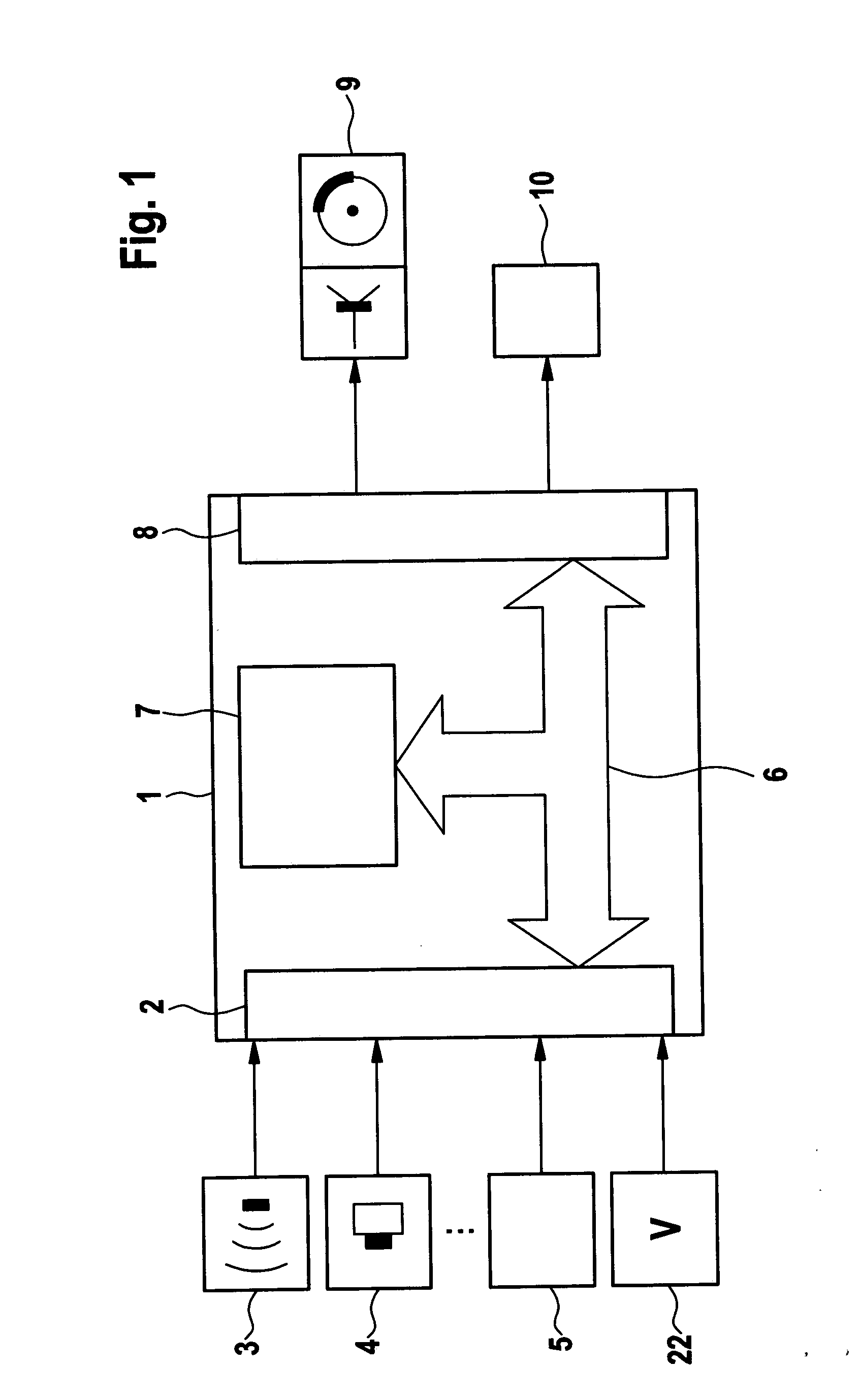
[0013]FIG. 1 shows a schematic block diagram of an exemplary embodiment of the device according to the present invention. This has an emergency braking control unit 1, which has an input circuit 2. Via input circuit 2, emergency braking control unit 1 can be supplied with input signals, these stemming from at least one object detection sensor system 3, 4. As object detection sensor system it is possible to provide a radar sensor, a lidar sensor, an ultrasonic sensor, a video sensor or a combination of these types of sensors. These sensors monitor the vehicle's surroundings, in particular the area in front of one's own vehicle, and detect the objects present within it. In this case, within the framework of the object sensor system, one or several sensors of one sensor type or several sensors of different sensor types may be used in order to be able to cover the surroundings of the vehicle sufficiently and to be able to identify relevant objects as relevant. In particular the combinat...


PUM


Abstract

A method and a device for triggering emergency braking of a vehicle for avoiding a collision or for reducing the severity of a collision, the vehicle having at least one object detection sensor, an ascertainment being made as a function of the detected objects as to whether a collision with an object is imminent and a risk to one's own vehicle in the event of a triggering of emergency braking being ascertained as a function of the current surrounding situation, the triggering threshold for emergency braking being variable in such a way that the probability for a false triggering is increased if a calculated risk posed by emergency braking is low and the triggering threshold for emergency braking being variable in such a way that the probability for a false triggering is lowered if a calculated risk posed by emergency braking is higher.

Description

FIELD OF THE INVENTION [0001] The present invention relates to a method and a device for triggering emergency braking of a vehicle for avoiding a collision or for reducing the severity of a collision, the vehicle having at least one object detection sensor, an ascertainment being made as a function of the detected objects as to whether a collision with an object is imminent and a risk to one's own vehicle in the event of a triggering of emergency braking being ascertained as a function of the current surrounding situation, the triggering threshold for emergency braking being variable in such a way that the probability for a false triggering is increased if a calculated risk posed by emergency braking is low and the triggering threshold for emergency braking being variable in such a way that the probability for a false triggering is lowered if a calculated risk posed by emergency braking is higher. BACKGROUND INFORMATION [0002] German Published Patent Application No. 102 31 557 descr...

Claims


Application Information

Patent Timeline
Patent Type & Authority Applications(United States)
IPC IPC(8): G08G1/16
CPCB60R21/0134G06K9/00805B60T7/22B60R2021/01259G06V20/58
Inventor LUCAS, BERNHARDWILHELM, ULFRANDLER, MARTIN
Owner ROBERT BOSCH GMBH
Why Eureka
Try Eureka