Adjoint-based design variable adaptation

a design variable and joint technology, applied in the field of joint-based design variable adaptation, can solve the problems of prohibitive practical situations and high demands of the final difference method

Inactive Publication Date: 2006-03-16
SUPERSONIC AEROSPACE INT
View PDF0 Cites 57 Cited by
  • Summary
  • Abstract
  • Description
  • Claims
  • Application Information

AI Technical Summary

Problems solved by technology

The finite difference method can therefore be very demanding and even prohibitive in practical situations.

Method used


Image

  • Adjoint-based design variable adaptation
  • Adjoint-based design variable adaptation
  • Adjoint-based design variable adaptation

Examples


Embodiment Construction

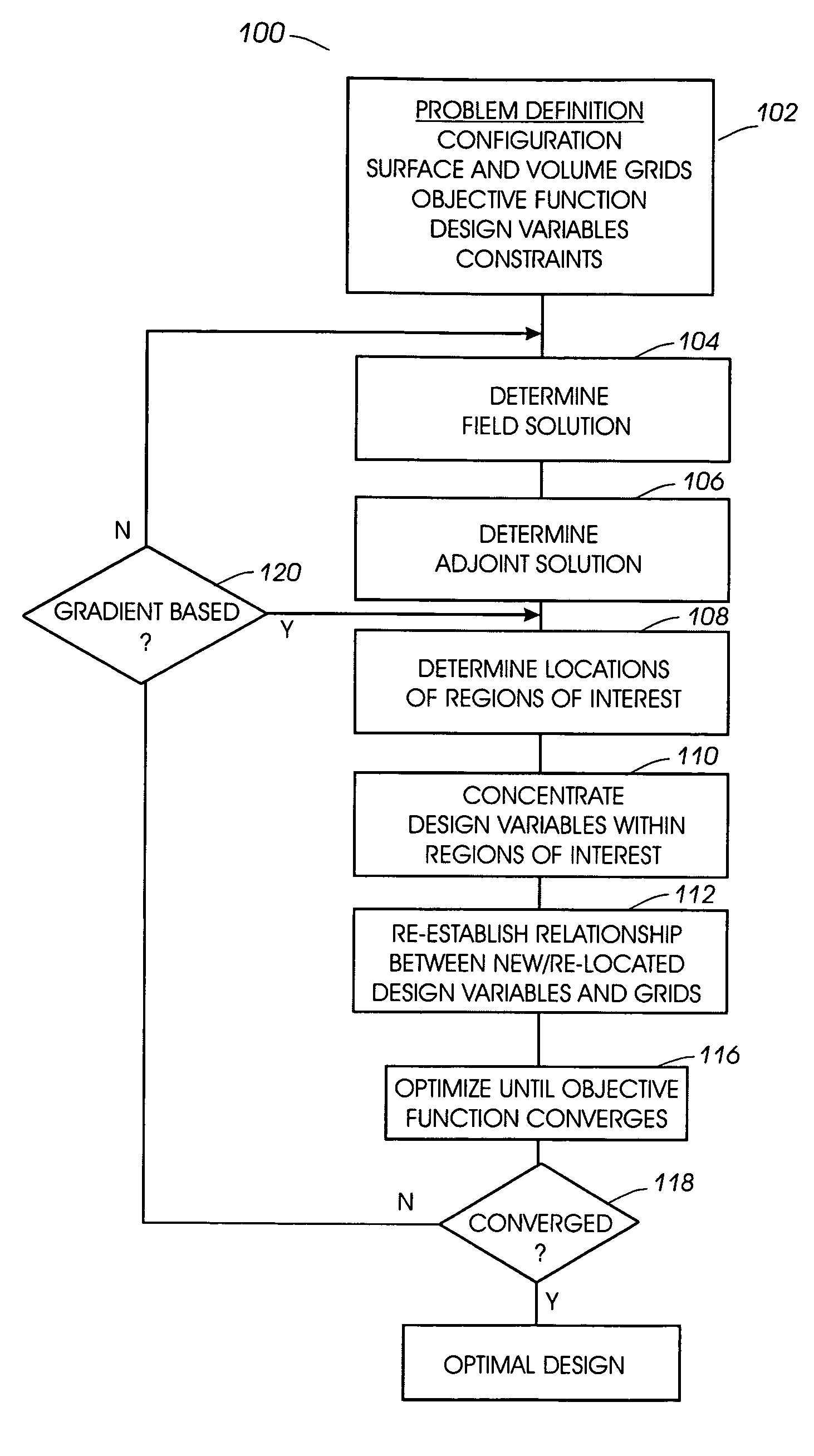
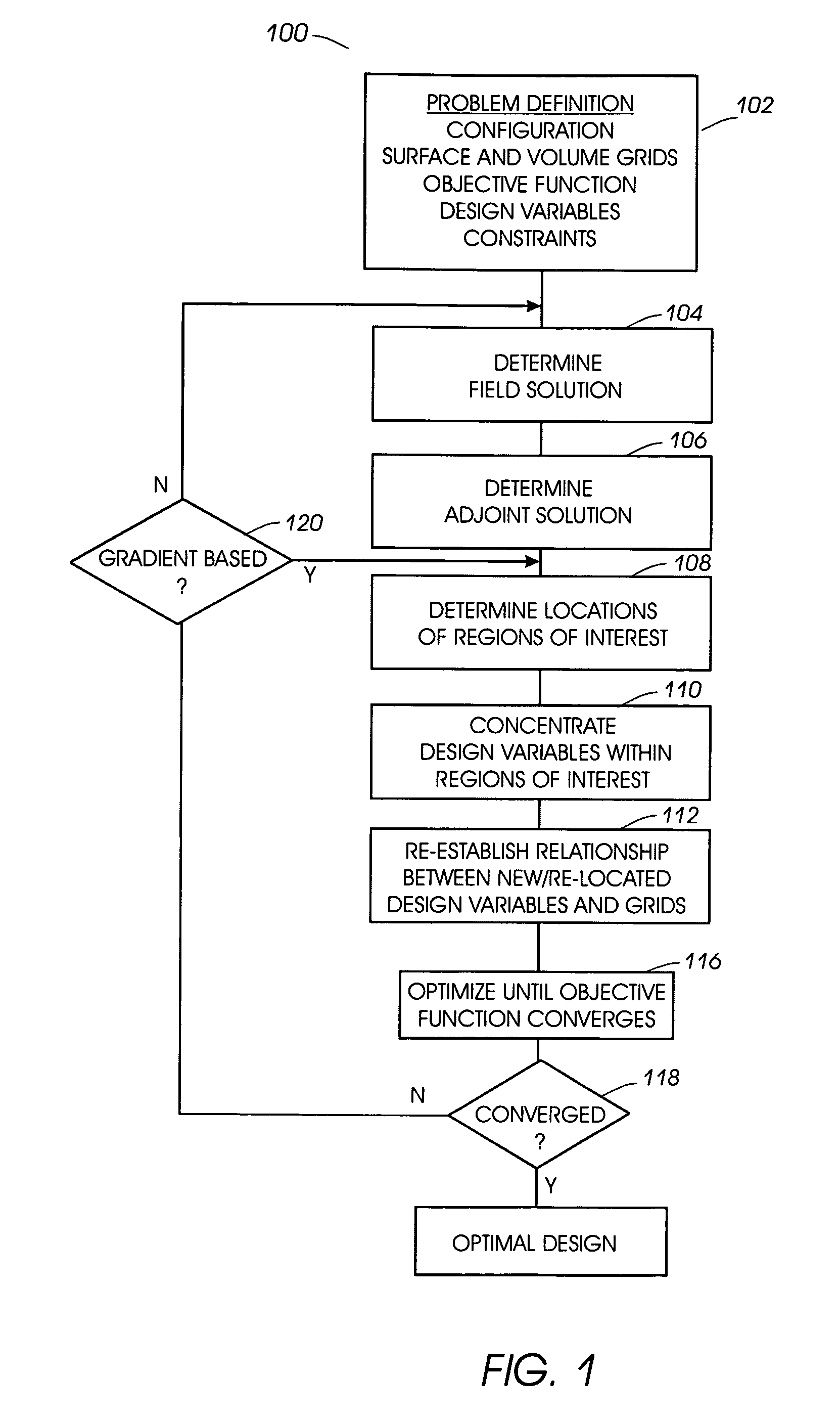
[0021] Referring to FIG. 1, a flow chart of a process 100 for refining the location of design variables used to analyze a product configuration is shown. After determining initial design variables, constraints, objective function, and surface grids in process 102, processes 104 and 106 combine computational field simulation with numerical optimization methods to compute a field solution and the corresponding adjoint solution, as described for instance in “Aerodynamic Shape Optimization using the Adjoint Method” by Antony Jameson, Lectures at the Von Karman Institute, Brussels, Feb. 6, 2003. Process 108 extends the adjoint method by determining regions of interest based on lines of equal magnitude (isocontours) in the adjoint field solution. Process 110 creates, removes, or re-locates design variables to the regions of interest. The relationships with the surface grids and corresponding sensitivities are re-established with the new design variables in process 112.

[0022] The ability ...


PUM


Abstract

A method for determining an optimum design includes determining an initial field solution for a design configuration based on an initial set of design variables; determining an adjoint solution to the field solution; determining the regions of interest on the design configuration based on magnitudes and/or gradients of the adjoint solution; and establishing design variables at the regions of interest.

Description

BACKGROUND OF THE INVENTION [0001] Computational simulation has come to play an increasingly dominant role in the engineering design process. Computer aided design (CAD) methods have essentially replaced the drawing board as the basic tool to define product configurations. Similarly, structural analysis is now almost entirely carried out by computational methods typically based on the finite element method. Commercially available software systems such as NASTRAN, ANSYS, or ELFINI have been progressively developed and augmented with new features, and can treat the full range of structural requirements. [0002] Computational fluid dynamics (CFD) is a computer-based technology that studies flluid dynamics. CFD involves building a computer-simulated model of a product, such as an airplane or race car, and then applying the laws of physics to the virtual prototype to predict the forces on various components of the product or the product's response in various operating conditions and envir...

Claims


Application Information

Patent Timeline
Patent Type & Authority Applications(United States)
IPC IPC(8): G06F17/10
CPCG06F17/5095G06F2217/08G06F2217/06G06F2111/04G06F2111/06G06F30/15
Inventor ARSLAN, ALAN E.MORGENSTERN, JOHN M.JORDAN, JOSIAH DAVID
Owner SUPERSONIC AEROSPACE INT
Why Eureka
Try Eureka