Supercharge Your Innovation With Domain-Expert AI Agents!

System and method for configuring a microcontroller clock system

a microcontroller clock and system configuration technology, applied in logic circuits, pulse automatic control, data conversion, etc., can solve the problems of time loss at the start-up, rapid start-up of the microcontroller, and leave the user with little flexibility

Inactive Publication Date: 2006-03-16
STMICROELECTRONICS SRL
View PDF7 Cites 9 Cited by
  • Summary
  • Abstract
  • Description
  • Claims
  • Application Information

AI Technical Summary

Benefits of technology

"The present invention aims to optimize the operation of a microcontroller by allowing for a secure and rapid start-up on a guaranteed clock frequency after a reset sequence or stop mode. Additionally, the invention provides the user with the ability to select the configuration of the clock system at any time. The invention includes a main oscillator, a phase locked loop, and a backup oscillator, which are activated in reset mode to generate a clock signal that is applied to the microcontroller to start it. The invention also includes first, second, and third circuitry to activate the backup oscillator and generate the clock signal for the microcontroller. The technical effects of the invention include improved reliability and flexibility in starting a microcontroller on a guaranteed clock frequency."

Problems solved by technology

In most microcontrollers using a quartz-type external resonator for the clock system, the oscillator stabilization phase for providing the clock signal causes a time loss at the start-up.
Furthermore, these constraints prevent a rapid start-up of the microcontroller after a reset sequence has been initiated or after a stop mode.
In addition, the configuration of the microcontroller operation, for example, the choice of a clock source from those available on the microcontroller in order to take into account requirements of the application, is either materially fixed, which leaves the user with little flexibility, or requires a step of reading an option word which is stored in the memory of the microcontroller.

Method used


Image

  • System and method for configuring a microcontroller clock system
  • System and method for configuring a microcontroller clock system
  • System and method for configuring a microcontroller clock system

Examples


Embodiment Construction

[0019] Preferred embodiments of the present invention will be described in detail hereinbelow with reference to the attached drawings.

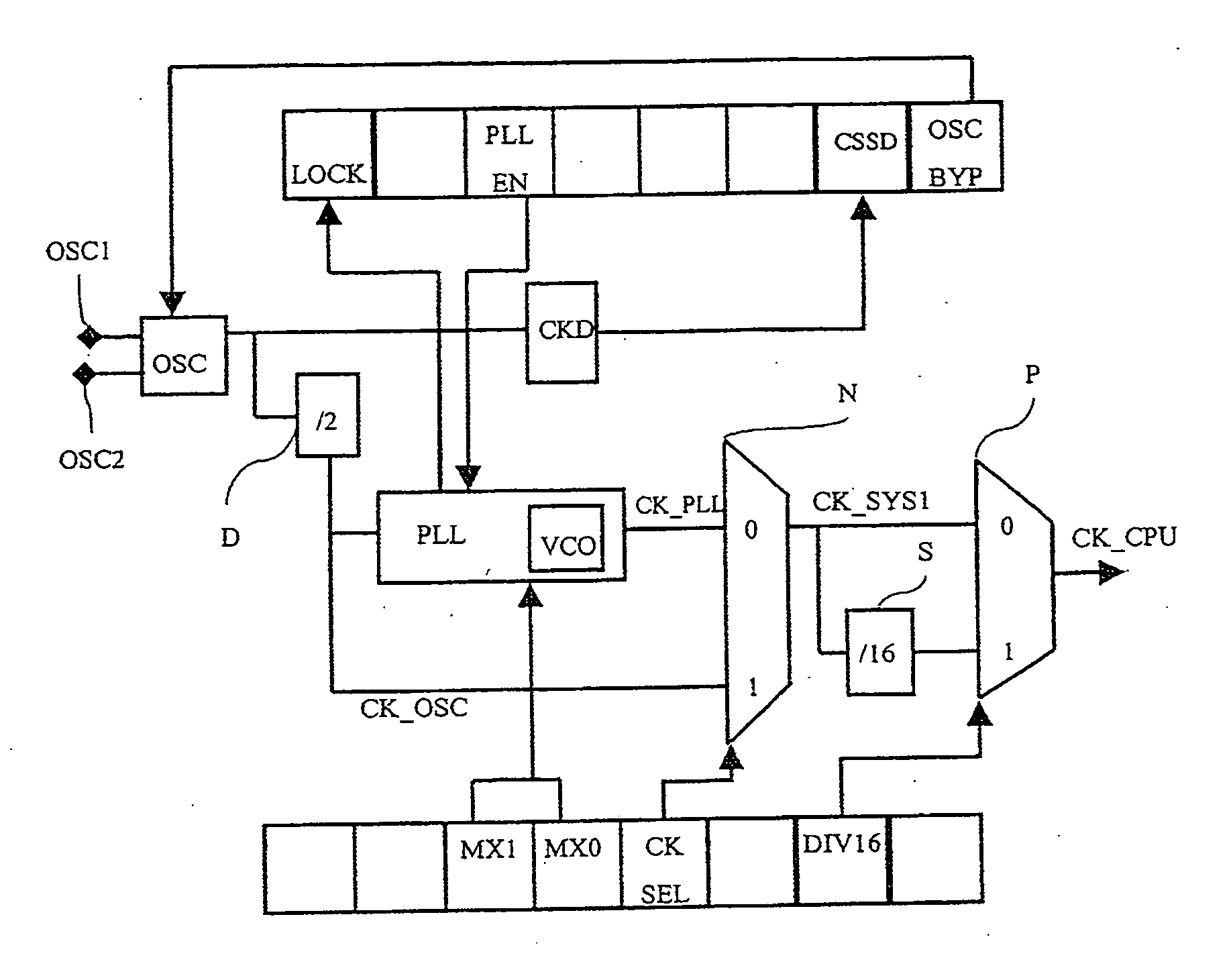
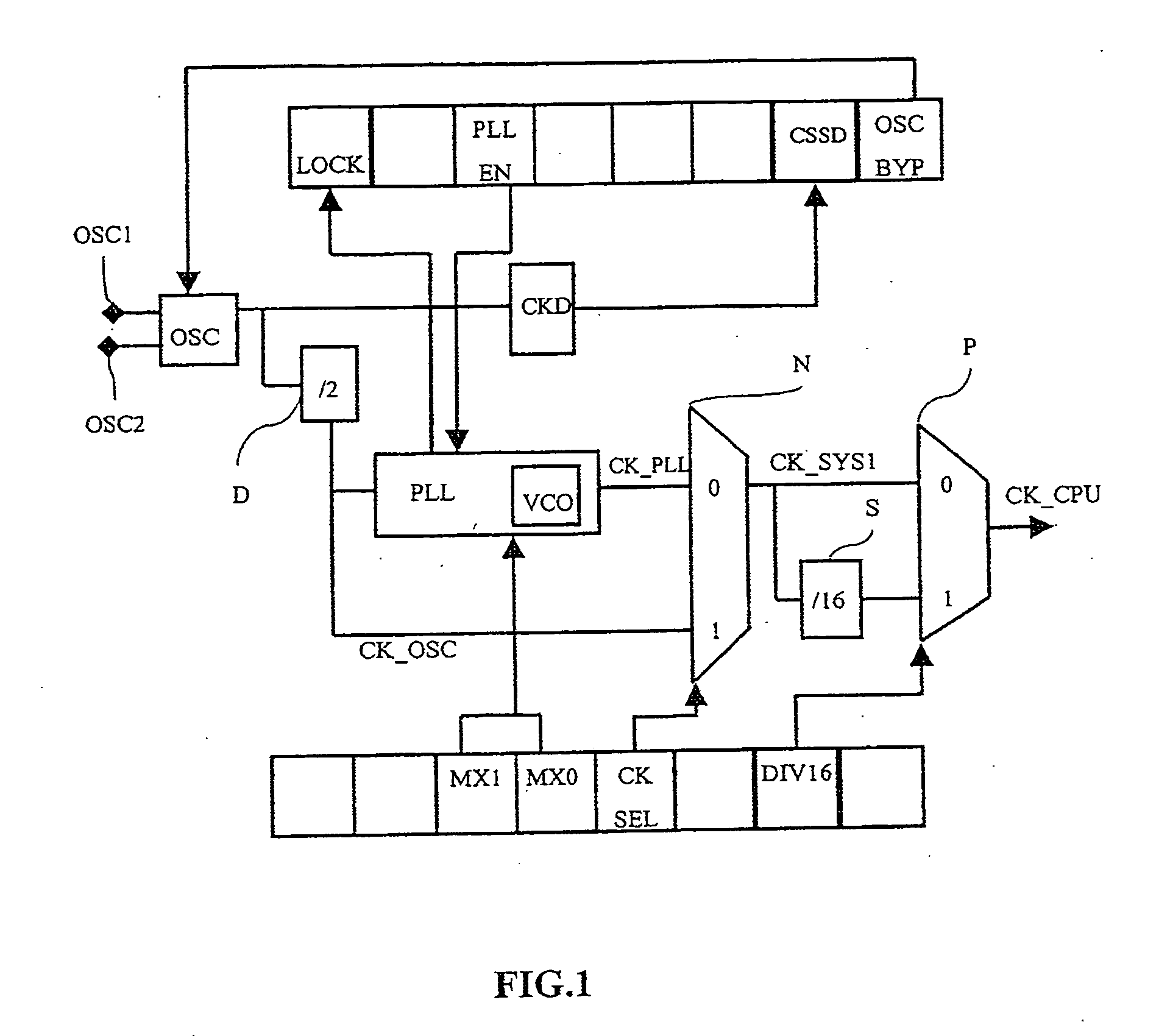
[0020] Preferred embodiments of the present invention provide a method for configuring a microcontroller clock system that includes a main oscillator. According to the method, the main oscillator and a backup oscillator are activated in reset mode, a clock signal is generated from the backup oscillator, and the clock signal is applied to the microcontroller to start it.

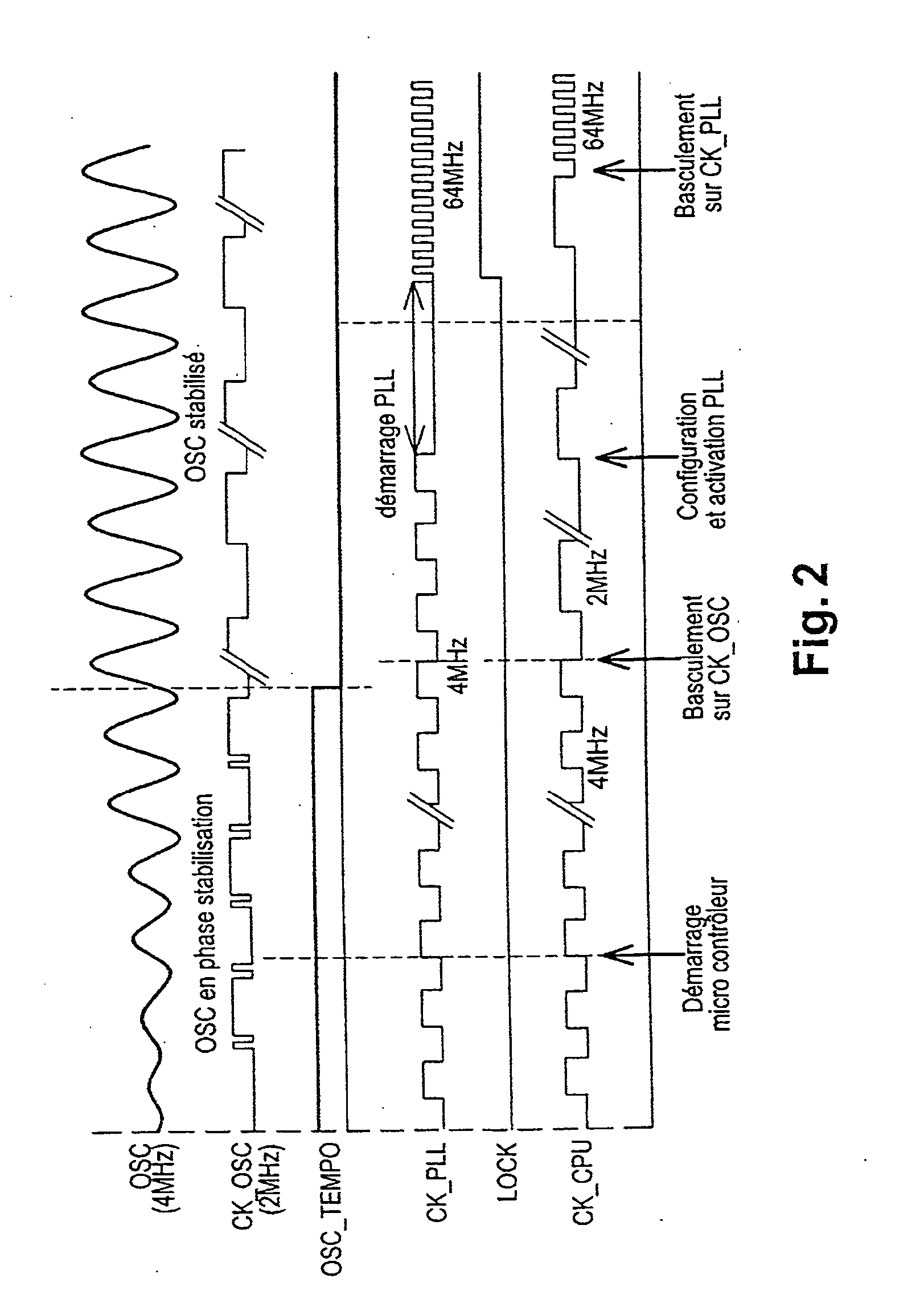
[0021] According to one embodiment, the main oscillator is switching over to, in order to generate the clock signal of the microcontroller when the main oscillator generates a stabilized signal. Preferably, the switchover to the main oscillator as the microcontroller clock source involves loading a selection bit of the main oscillator in a clock selection register of the microcontroller. In an exemplary embodiment, the switchover to the main oscillator as the microcontroller clock sou...


PUM


Abstract

A method is provided for configuring a microcontroller clock system that includes a main oscillator, a phase locked loop, and a backup oscillator. According to the method, the main oscillator and the backup oscillator are activated in reset mode. A clock signal is generated from the backup oscillator, and the clock signal that is generated is applied to the microcontroller in order to start the microcontroller. Also provided are a clock system for a microcontroller, and a microcontroller including a clock system.

Description

CROSS-REFERENCE TO RELATED APPLICATIONS [0001] This application is based upon and claims priority from prior French Patent Application No. 04 09307, filed Sep. 2, 2004, the entire disclosure of which is herein incorporated by reference. FIELD OF THE INVENTION [0002] The present invention relates to systems and methods for configuring a microcontroller clock system. BACKGROUND OF THE INVENTION [0003] A microcontroller includes a central processing unit CPU, which is the core of the microcontroller; a ROM, EPROM, EEPROM or Flash-EPROM-type central memory, which stores a program, referred to as the user program, that is loaded by the user prior to implantation of the microcontroller in the application; and an oscillator, which provides the main clock function of the microcontroller. The oscillator is provided to generate a clock signal, of which the frequency is typically approximately a dozen megahertz, which is used to activate the internal circuits of the microcontroller, in particu...

Claims


Application Information

Patent Timeline
Patent Type & Authority Applications(United States)
IPC IPC(8): G06F1/06G06F1/04G06F1/08
CPCG06F1/08
Inventor PLOURDE, OLIVIER
Owner STMICROELECTRONICS SRL
Features
  • R&D
  • Intellectual Property
  • Life Sciences
  • Materials
  • Tech Scout
  • Unparalleled Data Quality
  • Higher Quality Content
  • 60% Fewer Hallucinations
Learn More