Self-adhesive protective padding device

a protective padding and self-adhesive technology, applied in chemical protection, nuclear engineering, nuclear elements, etc., can solve the problems of young users' disapproval of devices that must be stepped into, and achieve the effect of sacrificing speed and ease of movement and increasing protection

Inactive Publication Date: 2006-03-23
MOSS PERRY VICTOR
View PDF14 Cites 34 Cited by
  • Summary
  • Abstract
  • Description
  • Claims
  • Application Information

AI Technical Summary

Benefits of technology

[0013] Unlike foam or gel pads, the “air bubble” pads' lightweight nature allo

Problems solved by technology

Young users also express distaste for devices that mus

Method used


Image

  • Self-adhesive protective padding device
  • Self-adhesive protective padding device
  • Self-adhesive protective padding device

Examples


Embodiment Construction

[0018] In describing the preferred and alternate embodiments of the present invention, as illustrated in the figures and / or described herein, specific terminology is employed for the sake of clarity. The invention, however, is not intended to be limited to the specific terminology so selected, and it is to be understood that each specific element includes all technical equivalents that operate in a similar manner to accomplish similar functions.

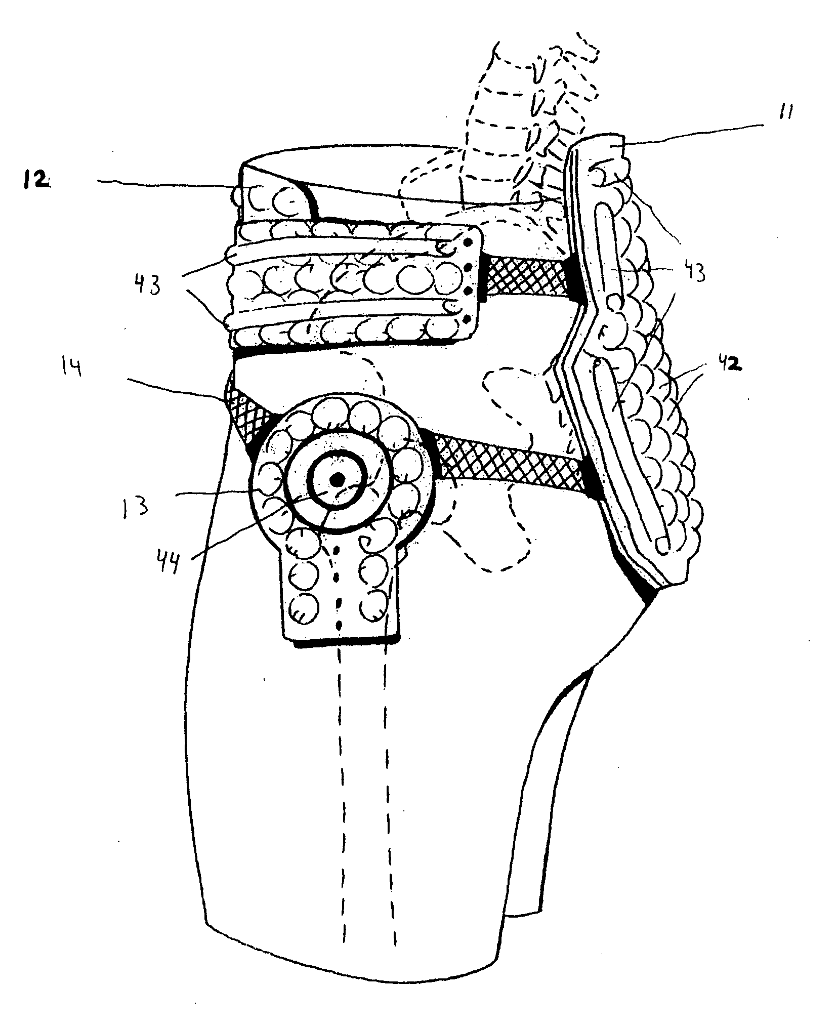
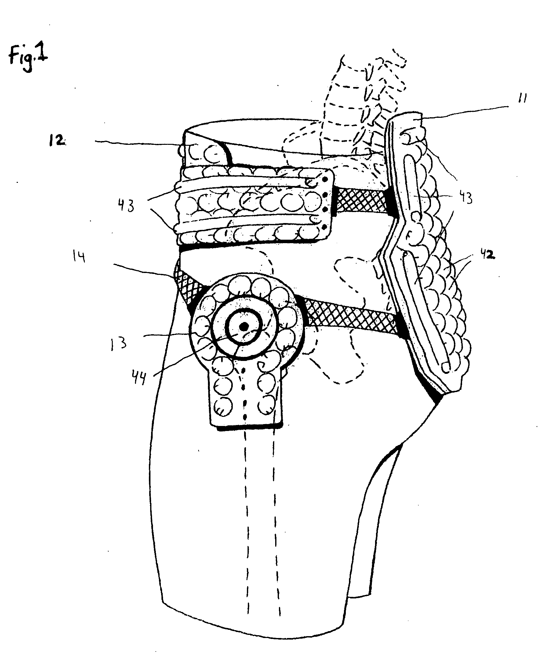
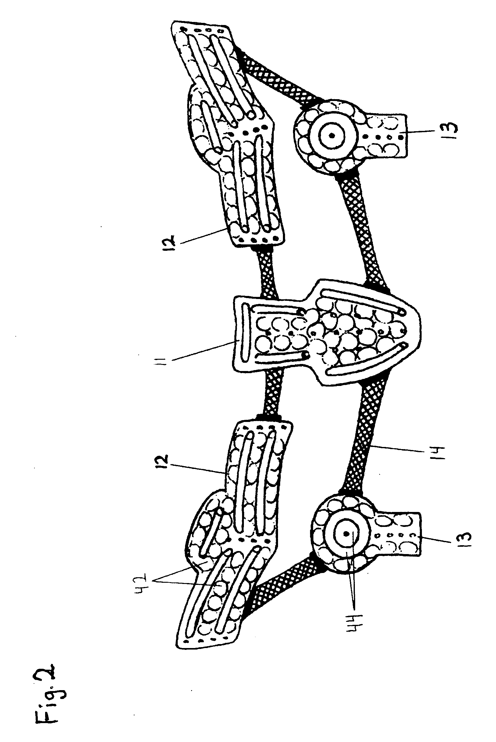
[0019] Referring now to FIG. 1, the present invention in a preferred embodiment uses five pads 11, 12, 13 and a mesh netting 14 for connecting the pads. In the preferred embodiment, two hip pads 12 substantially cover the iliac crest, anterior superior iliac spine, and posterior superior iliac spine. Two femur head pads 13 substantially cover the greater trichinae region. The rear pad 11 covers the lower lumbar spinal process, the transverse processes of the sacrum, and the upper area of the coccyx. The pads are connected to each other by th...


PUM


Abstract

A self adhesive protective padding device having a plurality of pads able to be adhered precisely to the hip and lower back areas of the body, wherein the padding being light weight and disposable, consisting of multi-layer air-filled material, is designed to protect the body from hip and bone fracture due to falls.

Description

FIELD OF THE INVENTION [0001] The present invention relates to a protective device. It is particularly concerned with protection of the femur head, the iliac crest, the lower lumbar region, the coccyx, and the sacrum of the person using the device. BACKGROUND OF THE INVENTION [0002] Hip fractures are a health problem of enormous proportion. Approximately 250,000 hip fractures occur annually in the United States, resulting in an estimated annual cost of over seven billion dollars in medical and nursing services. In the United States, the average cost of a hip fracture for all age groups in 1984 was $29,800. [0003] Over 98% of hip fractures are caused by falls. Growing evidence suggests that the strongest determinant of hip fracture risk in the event of a fall is the kinematical state of the body at the moment of impact. A simple fall from a standing height has several times the potential energy required to fracture a healthy hip. [0004] In order for a fall from a standing height to c...

Claims


Application Information

Patent Timeline
IPC IPC(8): A41D13/015A62B17/00
CPCA41D13/0506A41D13/0525A41D13/0562A41D13/0556A41D13/0537
Inventor MOSS, PERRY VICTOR
Owner MOSS PERRY VICTOR
Why Eureka
Try Eureka