Cup holder

a technology for cups and cups, applied in the field of cups, can solve the problems of increasing not only the number of parts, but also the steps required for assembly, and reducing the cost of construction, so as to improve the user experience and reliability of the unit, reduce the required machining precision, and increase the design flexibility

Inactive Publication Date: 2006-03-23
NIFCO INC
View PDF1 Cites 25 Cited by
  • Summary
  • Abstract
  • Description
  • Claims
  • Application Information

AI Technical Summary

Benefits of technology

[0019] The present invention described above has the following effects.
[0020] The invention of the first aspect ensures that the main holder member is always used in the normal projected condition with reduced numbers of components, as compared to those disclosed in patent reference 1 and 2, to thereby enable the unit to always hold containers stably, and improves the user friendliness and the reliability of the unit.
[0021] The invention of the second aspect allows the front edge section of the outer case to form the notched section, as in the case of the example of the invention, to thereby increase the design flexibility or reduce the required machining precision.
[0022] The invention of the third aspect can increase the tolerable range of container diameters, as compared to the conventional sub-holders, for the same holder diameter. This enables unit size reduction by reducing the size of the holder hole, which is worthwhile even by a small degree.
[0023] The invention of the fourth aspect can eliminate the possibility of catching the rim at the bottom periphery or narrower section of a container when pulling it out of the holder hole, since the sub-holder is tilted upward. In the present invention, moreover, even when a container that is extremely narrow tilts towards the sub-holder in the holder hole, the sub-holder tilted upward eliminates the possibility of inadvertent falling of the container, unlike the conventional sub-holders that are arranged horizontally or tilted slightly downward.

Problems solved by technology

This makes the construction complex and cost reduction difficult, as it increases not only the number of parts, but also the steps required for assembly.

Method used


Image

  • Cup holder
  • Cup holder
  • Cup holder

Examples


Embodiment Construction

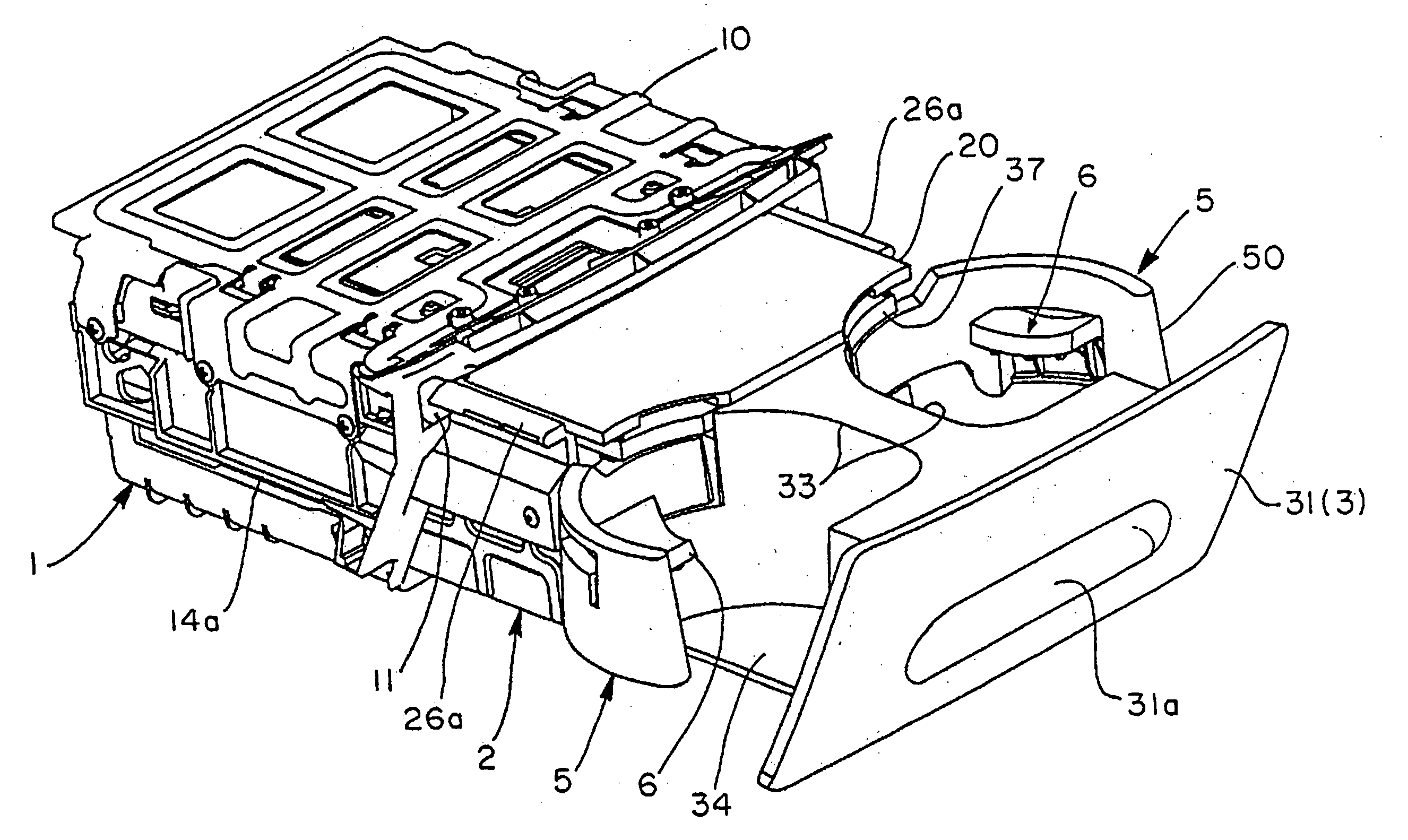
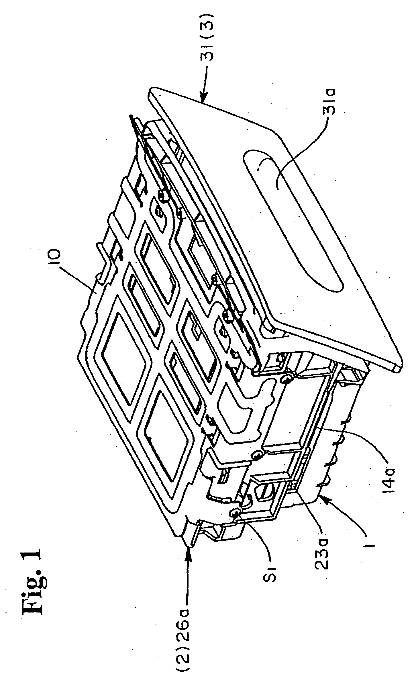
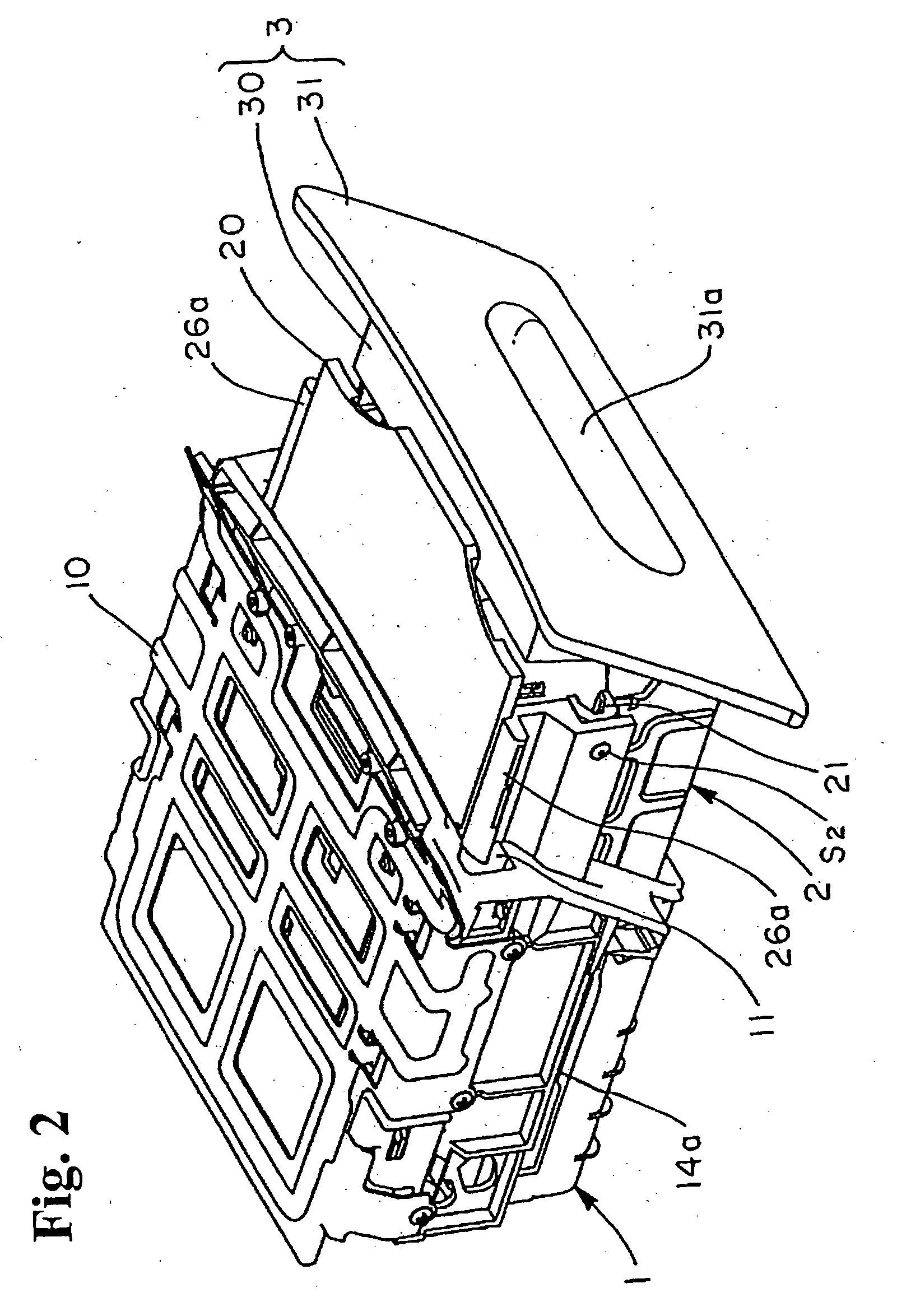
[0041] Embodiment of the present invention will be explained based on the drawings. FIGS. 1-3 are schematic views of a cup holder unit in various states. FIGS. 4-6 and 8(a)-8(c) show the components of the unit. FIGS. 7, 9(a) and 9(b) show the relationship between the side supporter and the sub-holder. FIGS. 10-15 show the switching operation of the unit, and FIGS. 16(a) and 16(b) schematically compare the sub-holder of the present invention with that of a conventional unit. In the following explanation, the unit's structure will be discussed in detail, and then how to use the unit, or the operation, will be mentioned.

Unit's Structure

[0042] A cup holder unit in this embodiment is installed in an instrument panel or a console of various types in an automobile, for example, and the main components include a fixed outer case 1, a movable inner case 2, a main holder member 3 for holding a container, a connecting member 4 pivotally supported in the inner case 2, side supporters 5 pivot...


PUM


Abstract

A cup holder unit includes an outer case, an inner case slidable between a pulled-out position and a stored position, a main holder member slidable between a usable position and a non-usable position, and a connecting member pivotally supported on the inner case. The connecting member has an abutment section to abut against a corresponding section of the main holder member halfway through pulling of the main holder member from the non-usable position so that the main holder member can be pulled out together with the inner case, and a tab to engage a notched section when the inner case is substantially fully pulled out to the pulled-out position. A disengaging abutment section is formed at the connecting member to disengage the tab from the notched section by abutting against the corresponding section halfway through pushing the main holder member from the usable position to the non-usable position.

Description

BACKGROUND OF THE INVENTION AND RELATED ART STATEMENT [0001] The present invention relates to a cup holder for holding a container of various types, and particularly to a drawer-type cup holder installed in an encased condition in an instrument panel or a console of various types in an automobile that is pulled out for use as needed. [0002] There is a so-called two-stage, drawer-type cup holder, as exemplarily shown in patent references 1 and 2, wherein an inner case is arranged in an outer case so that the position of the inner case is slidably switched relative to the outer case, and a main holder member arranged in the inner case so that the position of the main holder member is slidably switched relative to the inner case. A cup holder of this type makes it possible, for example, to reduce the front-to-back dimension of the unit as a whole, or set the pulled-out position of the main holder member more forward in accordance with the length of the inner case while controlling the ...

Claims


Application Information

Patent Timeline
Patent Type & Authority Applications(United States)
IPC IPC(8): A47K1/08
CPCB60N3/106B60N3/102
Inventor YANAGITA, YOUSUKEHONDA, ITSUO
Owner NIFCO INC
Why Eureka
Try Eureka