

Circuit breaker with a moveable plug contact
a plug contact and circuit breaker technology, applied in circuit breakers, circuit breakers for excess current, protective switch terminals/connections, etc., can solve problems such as the possibility of severe load on enclosure parts such as plug contacts, which are composed of plastics
- Summary
- Abstract
- Description
- Claims
- Application Information
AI Technical Summary
Benefits of technology
Problems solved by technology
Method used
Image

Examples
Embodiment Construction
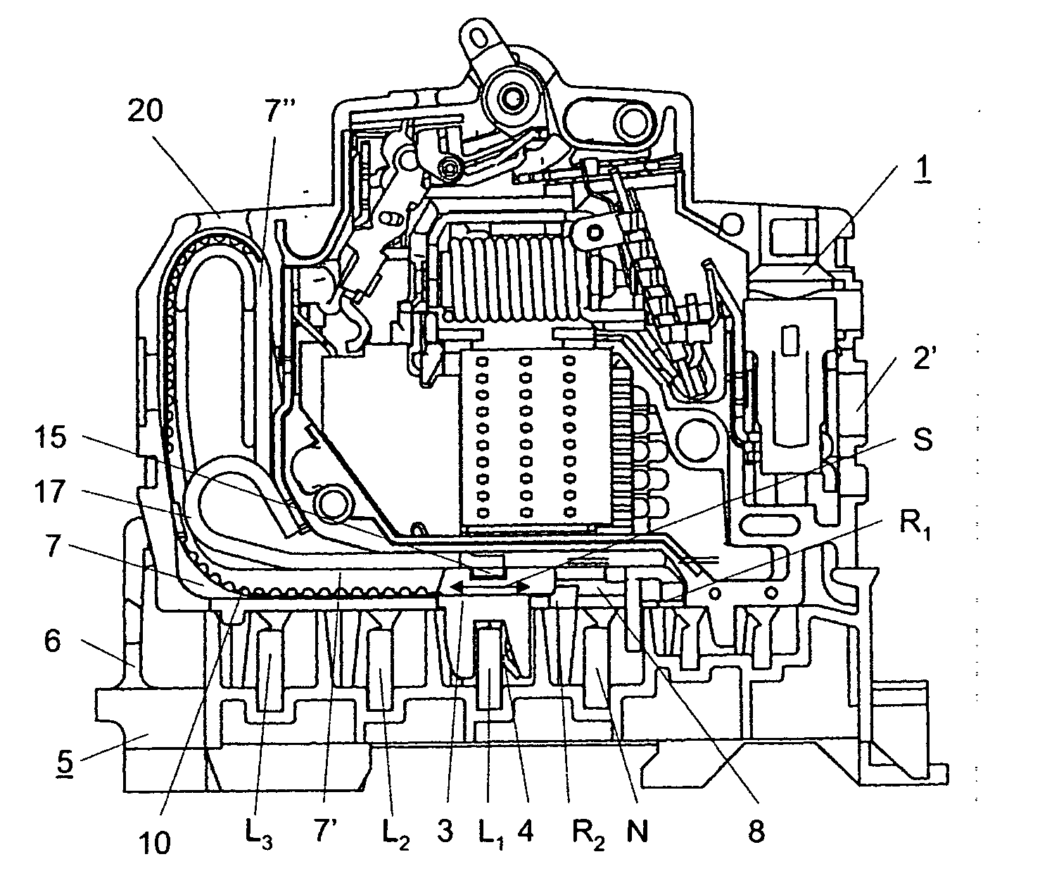
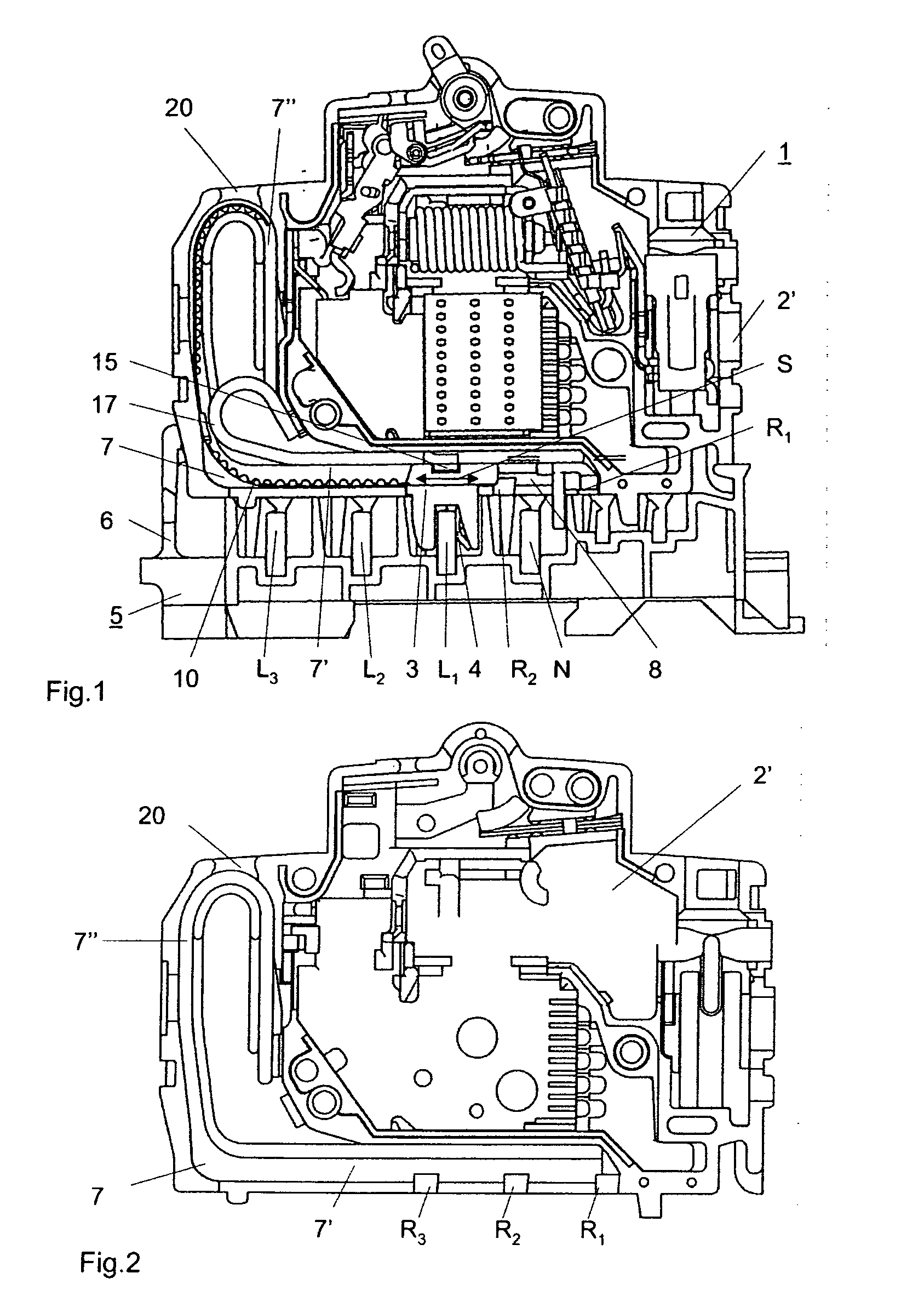
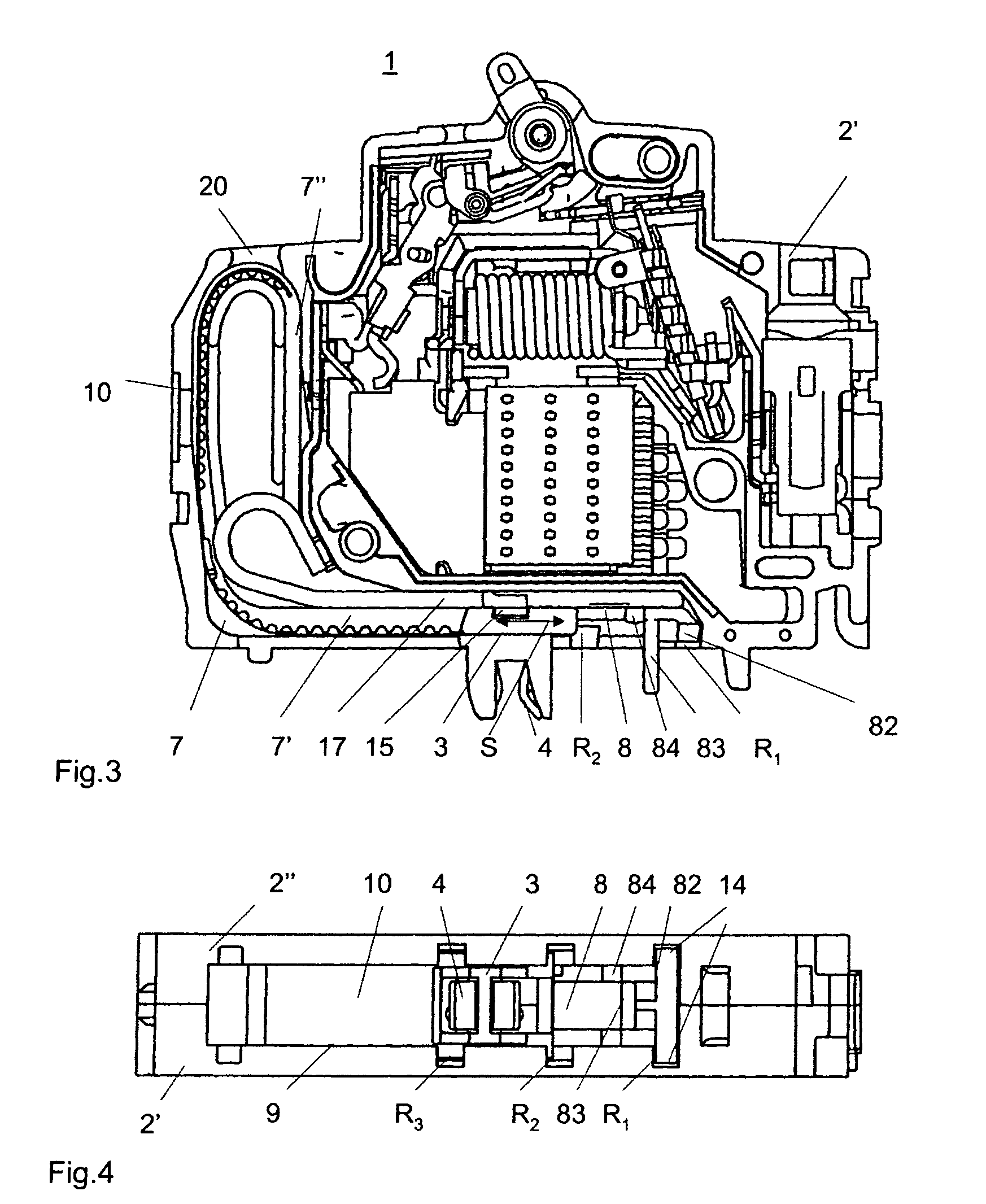
[0003] The invention as it is specified in the patent claims is based on the object of providing a circuit breaker of the type mentioned initially in which pole conductor changes can be carried out quickly and with little effort, in particular without the use of any tools.
[0004] In a circuit breaker according to the invention, the plug contact is held on a contact mount which can be moved transversely with respect to the busbars and can be locked to the circuit breaker enclosure. These measures mean that, when a pole conductor change takes place, the plug contact now no longer need be removed from the circuit breaker enclosure, or be reinserted into the circuit breaker enclosure at a different position again, but that the plug contact can remain in the circuit breaker enclosure and is just moved to the position associated with another busbar and another pole conductor. The method steps involved in this process, specifically the unlocking, movement and locking, can in practice be ca...
PUM
 Abstract
Description
Claims
Application Information