Image forming apparatus and toner

a technology of image forming apparatus and toner, which is applied in the direction of electrographic process apparatus, corona discharge, instruments, etc., can solve the problems of abnormal picture, pollution of the surface of photoconductor, and pollution of the surface of the charging member, so as to reduce the amount of toner and/or carrier, the effect of precise gap and high-quality pictures

Active Publication Date: 2006-03-23
RICOH KK
View PDF6 Cites 13 Cited by
  • Summary
  • Abstract
  • Description
  • Claims
  • Application Information

AI Technical Summary

Benefits of technology

[0009] A first more specific object of the present invention is to provide an improved image forming apparatus that can reduce the amount of toner and / or carrier adhering to gap control materials.
[0010] A second more specific object of the present invention is to provide an improved image forming apparatus that can substantially maintain a precise gap between the charging roller and photoconductor and print high-quality pictures over a long term.
[0014] According to benefits realized by the present invention, it is possible to provide an image forming apparatus that can substantially maintain a precise gap and print the high-quality pictures in the long term even if polymerization toner is used.

Problems solved by technology

Thus, when the charging roller is left in the state that it is pushed against the surface of photoconductor for a long term, a material (for example, plasticizer) included in the charging roller releases from the surface of the charging roller, and it pollutes the surface of photoconductor.
In addition, as charging with electricity is performed in the state that the charging member (such as charge roller) contacts the surface of the image bearing member (such as photoconductor), the residual toner, which remains after the image transferring, on the surface of the image bearing member is transferred to the surface of the charging member and induces pollution on the surface of the charging member.
This toner and / or carrier bonding to the gap tape causes an abnormal picture due to periodic gap changes that cause a changing electric charging current.
In addition, the toner and / or carrier bonding to the tape spacers causes an increase in quantity of ozonea, and may cause damage to the photoconductor.

Method used


Image

  • Image forming apparatus and toner
  • Image forming apparatus and toner
  • Image forming apparatus and toner

Examples


Embodiment Construction

[0024] Embodiments of the invention are explained below based on the drawings. However, the present invention is not limited to the specifically disclosed embodiments, and variations and modifications may be made without departing from the scope of the present invention.

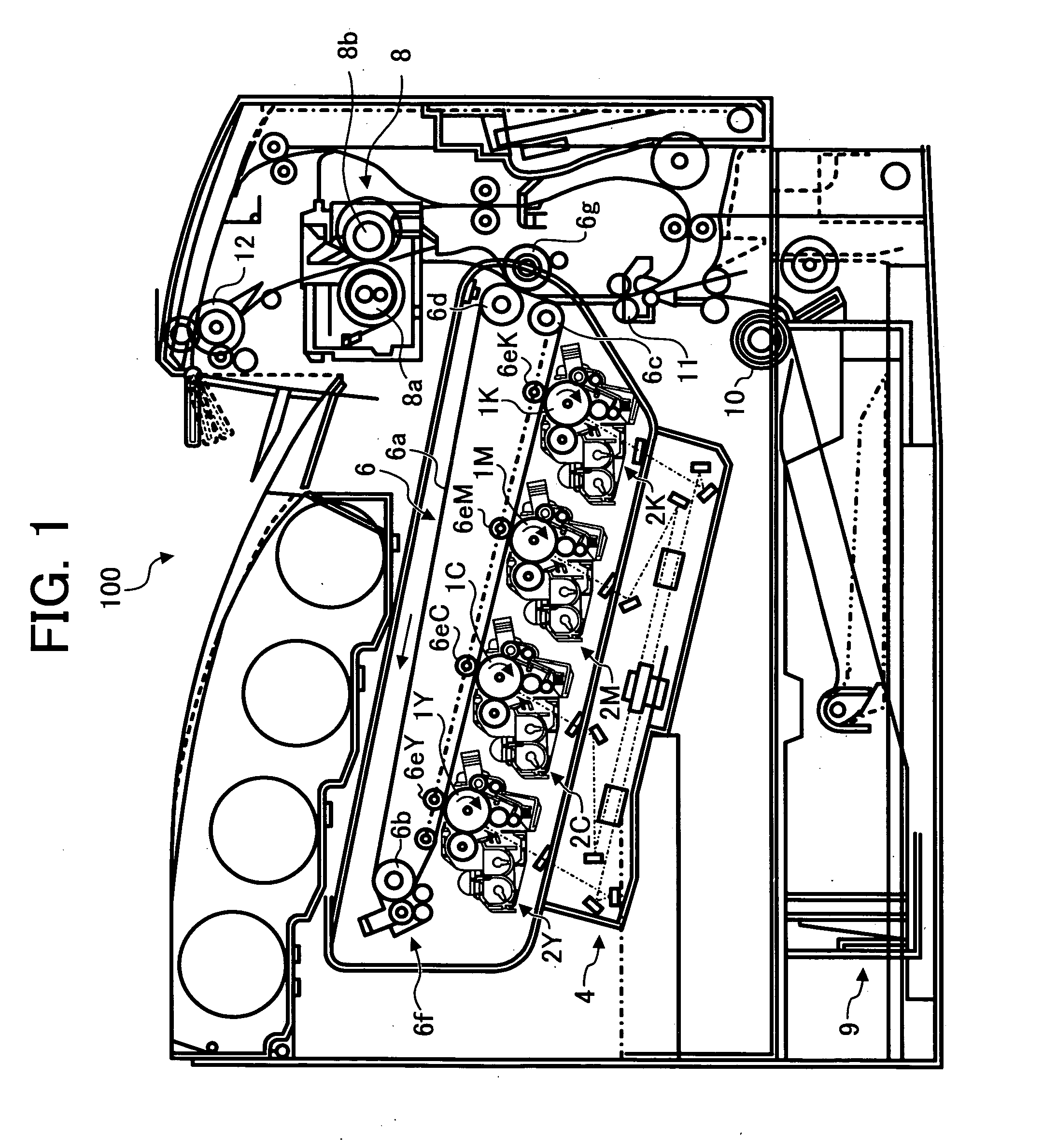
[0025]FIG. 1 is an elevation view showing an image forming apparatus 100 according to an embodiment of the present invention. Preferably, the image forming apparatus 100 uses electrophotography. The image forming apparatus 100 is referred to as “tandem image forming apparatus” and forms color images by using four color toners. The four color toners are yellow, cyan, magenta and black (hereinafter referred to as Y, C, M and K, respectively). This image forming apparatus 100 has four photoconductors 1Y, 1C, 1M and 1K as the latent image bearing members which are contained in image forming units 2Y, 2C, 2M and 2K, respectively. In this embodiment, the photoconductor 1 including a photoconductive drum is used, but a pho...


PUM


Abstract

An image forming apparatus having an image support body configured to support a latent image, a charging member configured to provide a substantially uniform charge to a surface of the image support body and a spacer coupled to the charging member and configured to contact the image support body to maintain a gap between the image support body and the charging member. A cleaning part is configured to clean the surface of the image support body after developer is applied to the image support body and transferred to a recording medium. The cleaning part is configured to satisfy the relationship A+B≦C, where A is a width of the effective charging area of the charging member that charges a surface of the image support body, B is a total width of the spacer that contacts the image support body, and C is a width of cleaning part that contacts the image support body.

Description

CROSS-REFERENCE TO RELATED APPLICATIONS: [0001] This document claims priority and contains subject matter related to Japanese Patent Applications Nos. 2004-271917 and 2004-335310, filed on Sep. 17, 2004 and on Nov. 19, 2004 respectively, the entire contents of each of which are hereby incorporated herein by reference. FIELD OF THE INVENTION [0002] The present invention relates to an electrophotographic image forming apparatus such as a copier, a printer, or a facsimile. In addition, the present invention also relates to an image forming apparatus using a non-contact charging device, and a toner used in the image forming apparatus. BACKGROUND OF THE INVENTION DISCUSSION OF BACKGROUND [0003] In an electrophotographic image forming apparatus such as a copier, a printer, or a facsimile, a photoconductor is uniformly electrified or charged by various methods before forming an electrostatic latent image on the surface of the photoconductor. Recently, a charging roller with an electrocondu...

Claims


Application Information

Patent Timeline
Patent Type & Authority Applications(United States)
IPC IPC(8): G03G15/00G03G15/02G03G21/00
CPCG03G15/025G03G15/0233
Inventor KAWASUMI, MASANORIMIZUISHI, HARUJIOJIMI, TOKUYAKOIKE, TOSHIOSHINTANI, TAKESHIARAI, YUJIYONEDA, TAKUZIAMEMIYA, KENTAWADA, TAKAAKITOMITA, MASAMIUCHITANI, TAKESHIKUWAHARA, NOBUONAGASHIMA, HIROYUKIYANAGIDA, MASATO
Owner RICOH KK
Why Eureka
Try Eureka