Device and a method for treatment of atrioventricular regurgitation

a technology for atrioventricular regurgitation and a device, applied in the field of devices for treating atrioventricular regurgitation, can solve the problems of reducing the function of the left ventricle, creating insufficiency, and insufficient heart function

Inactive Publication Date: 2006-03-23
EDWARDS LIFESCIENCES CORP
View PDF99 Cites 153 Cited by
  • Summary
  • Abstract
  • Description
  • Claims
  • Application Information

AI Technical Summary

Benefits of technology

[0013] Thus, a device for treatment of atrioventricular regurgitation comprises a suturing means having such dimensions as to be introducible, via blood vessels leading to the heart, to two leaflets of an atrioventricular valve between an atrium and a corresponding ventricle of the heart and being designed for binding together the two leaflets in a position along the free edges of the leaflets, whereby the closing of the atrioventricular valve is improved.
[0034] As a result, the suturing means can easily be made to transform from its first state to its second and thereafter maintain its second state.

Problems solved by technology

This will lead to a reduced functionality of the left ventricle and subsequently to heart insufficiency, which is a mortal disease.
Any one or all of these in different combinations may be injured and create insufficiency.
To certain groups of patients this is particularly hazardous and there is an apparent risk of not surviving the operation.
The mechanical valve carries the risk of thromboembolism and requires anticoagulation, with all its potential hazards, whereas biological prostheses suffer from limited durability.
Another hazard in connection with replacement is the risk of endocarditis.
The techniques of mitral valve repair rely on decreasing valve area to increase leaflet apposition, but fail to address subvalvular dysfunction.
Mitral insufficiency caused by prolapse of the anterior leaflet, posterior leaflet with calcified annulus, or prolapse of both leaflets constitutes a more demanding challenge to repair.

Method used


Image

  • Device and a method for treatment of atrioventricular regurgitation
  • Device and a method for treatment of atrioventricular regurgitation
  • Device and a method for treatment of atrioventricular regurgitation

Examples


Embodiment Construction

[0051] The device will now be described with reference to its use on a mitral valve. However, it is obvious that the device could also be used on the two biggest leaflets of the tricuspid valve.

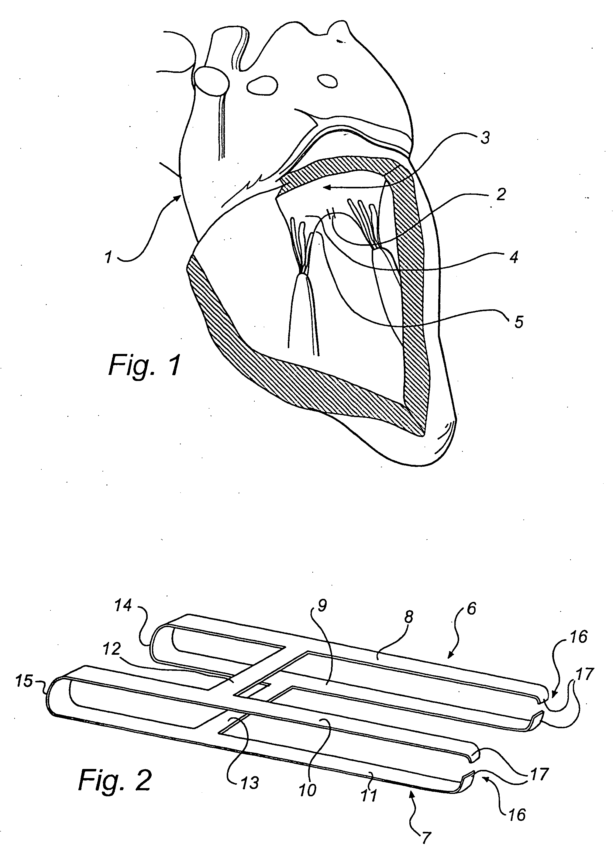
[0052]FIG. 1 shows a heart 1. The left side of the heart 1 is shown in section. A clip constituting a suturing means 2 is applied to the free edges of the mitral valve 3 keeping the mitral leaflets 4, 5 together in a connection point so as to create a double orifice, one orifice on each side of the connection point, thus allowing the leaflets 4, 5 to close completely.

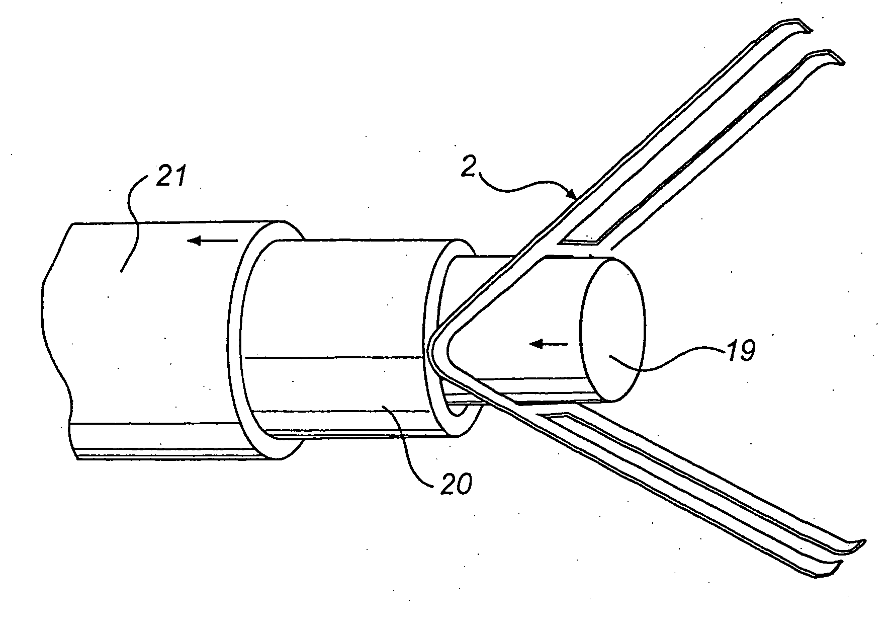
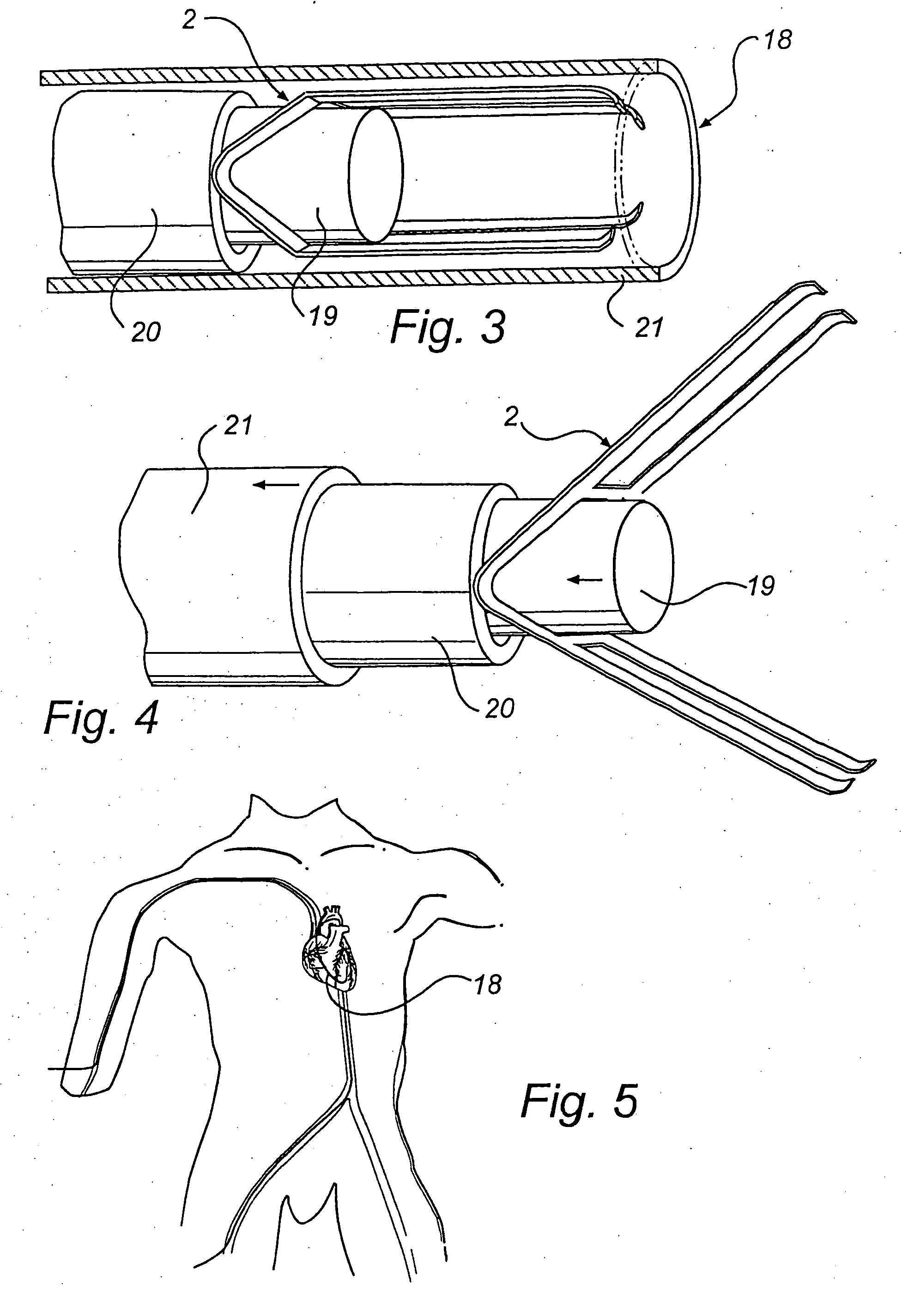
[0053] In the following there will be described a device and a method for creating a double orifice in the mitral valve 3 of a beating heart 1.

[0054] Referring now to FIG. 2, an enlargement of the suturing means 2 is showed. The suturing means 2 being a clip consists of two pairs 6, 7 of arms 8-9 and 10-11. The arms 8-9 and 10-11 in the pairs are connected in one end 14, 15 and thus are formed in one piece. In their other end ...


PUM


Abstract

A device and method for treatment of atrioventricular regurgitation comprises a suturing device. The suturing device is configured to be introducible, via blood vessels leading to the heart, to two leaflets of the atrioventricular valve between the atrium and a corresponding ventricle of the heart. The suturing device is configured for binding together the two leaflets along the free edges of the leaflets. A method of using the device includes inserting the suturing device into a catheter, introducing the catheter to the heart and positioning a distal end of the catheter close to two leaflets of an atrioventricular valve, capturing the free edges of the two leaflets with the suturing device in its open state, binding together the two leaflets by transition of the suturing device into its closed state, and retracting the catheter from the heart. As a result, the closing of the valve is improved.

Description

CROSS REFERENCE TO RELATED APPLICATIONS [0001] The present application is a continuation of co-pending U.S. application Ser. No. 10 / 383,596, filed Mar. 10, 2003 under the same title, which is a continuation of U.S. application Ser. No. 09 / 670,082, filed Sep. 6, 2000 under the same title, now U.S. Pat. No. 6,719,767.BACKGROUND OF THE INVENTION [0002] The invention relates to a device for treatment of atrioventricular regurgitation and a method for treatment of atrioventricular regurgitation using said device. [0003] The heart has two atrioventricular valves, the mitral valve, which is situated between the left atrium and the left ventricle, and the tricuspid valve situated between the right atrium and the right ventricle. The tricuspid valve has three leaflets, two of which are much bigger than the third. These two bigger leaflets could be considered to correspond to the two leaflets of the mitral valve. Therefore, only the mitral valve will hereinafter be discussed although correspo...

Claims


Application Information

Patent Timeline
Patent Type & Authority Applications(United States)
IPC IPC(8): A61B17/08A61BA61B17/00A61B17/064A61B17/122A61F2/24
CPCA61B17/064A61B17/0644A61B17/122A61F2/2442A61B2017/00783A61B2017/00867A61B2017/0641A61B2017/00243
Inventor KIMBLAD, PER OLA
Owner EDWARDS LIFESCIENCES CORP
Why Eureka
Try Eureka