

Pressure detecting mat and antidecubitus system provided with the same
a technology of anti-decubitus and pressure detecting mat, which is applied in the direction of force/torque/work measurement apparatus, instruments, applications, etc., can solve the problem of inability to make fine pressure detection
- Summary
- Abstract
- Description
- Claims
- Application Information
AI Technical Summary
Benefits of technology
Problems solved by technology
Method used
Image

Examples
first embodiment
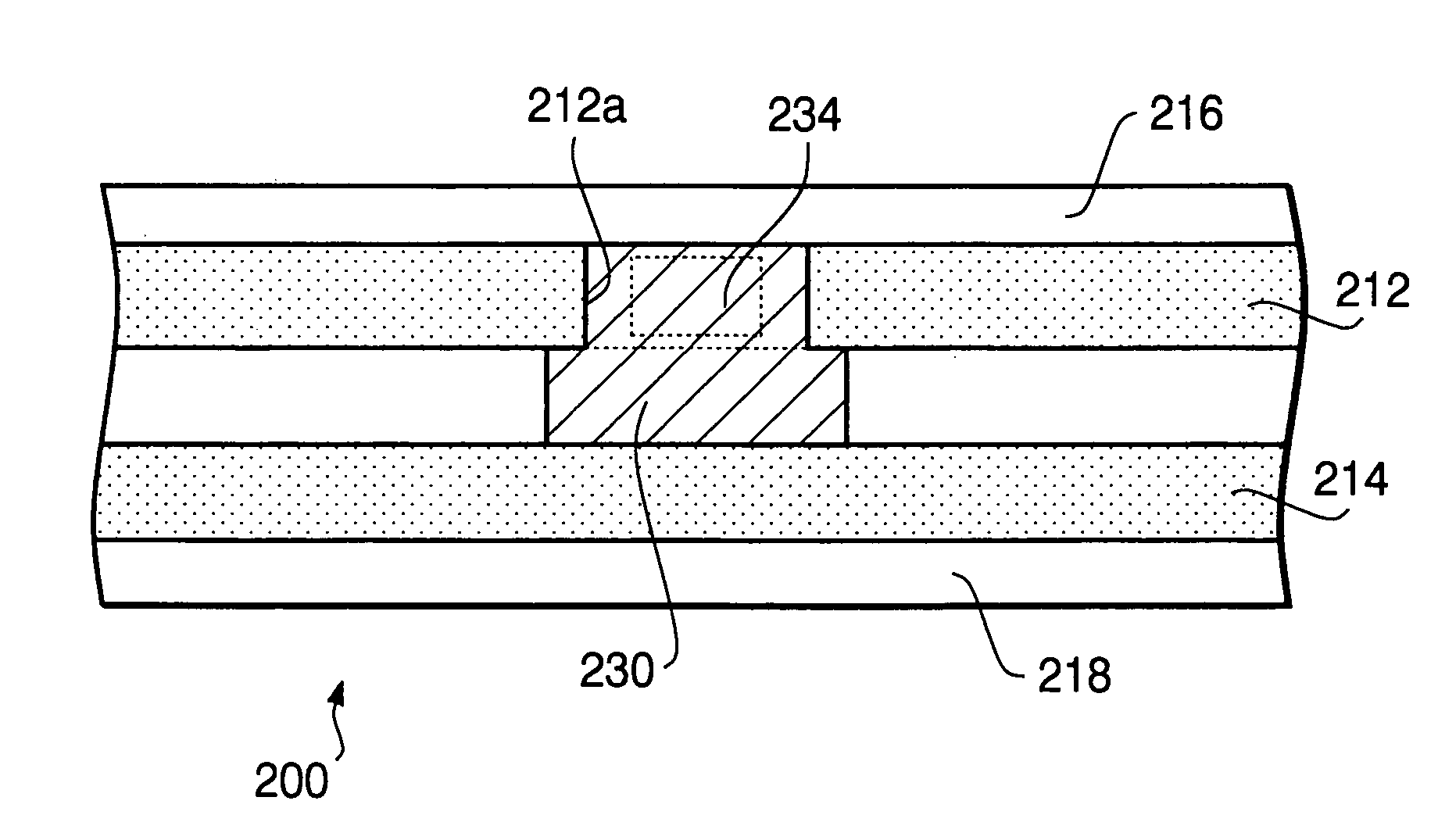
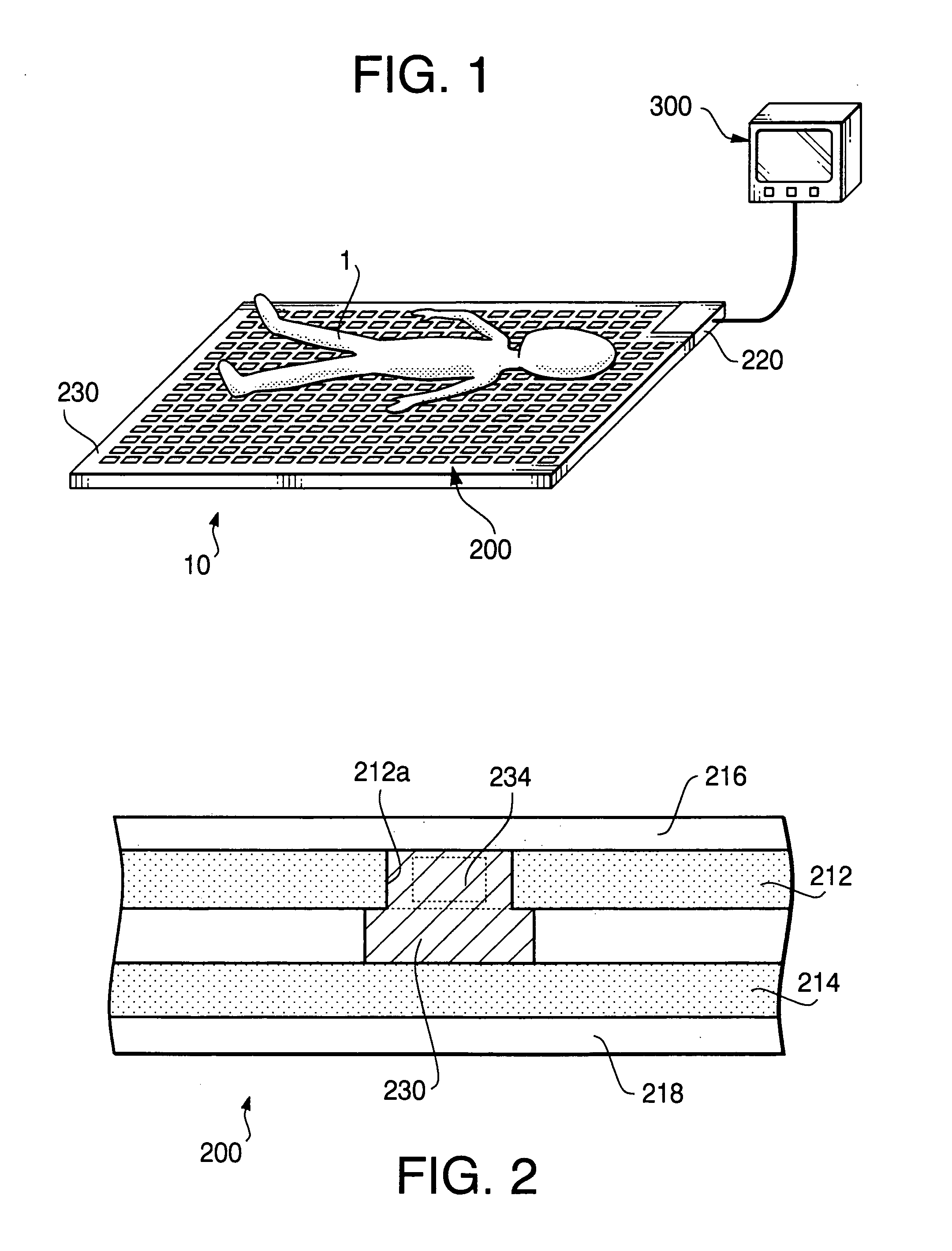
[0041]FIG. 2 shows the cross-sectional structure of the pressure-detecting mat 200. The pressure-detecting mat 200 utilizes a substrate using a two dimension diffusive signal-transmission technology (which is briefly explained in http: / / www.utri.co.jp / biz / index02—02.html at the time of Sep. 15, 2005, and hereinafter, is simply referred to as a 2D-DST), or utilizes a part of the constitution of a communication device disclosed in Japanese Patent Provisional Publication No. P2003-188882 (that is, a device which sends packets of desired data to a destination by connecting each adjacent couple of a plurality of chips in an insulating layer with one another using two conductive layers, the insulating layer being sandwiched by the two conductive layers and formed with the plurality of chips scattered therein), and is provided with four laminated layers in total, i.e., two conductive layers 212 and 214, and two insulating layers 216 and 218 for electrically isolating the conductive layers ...
second embodiment
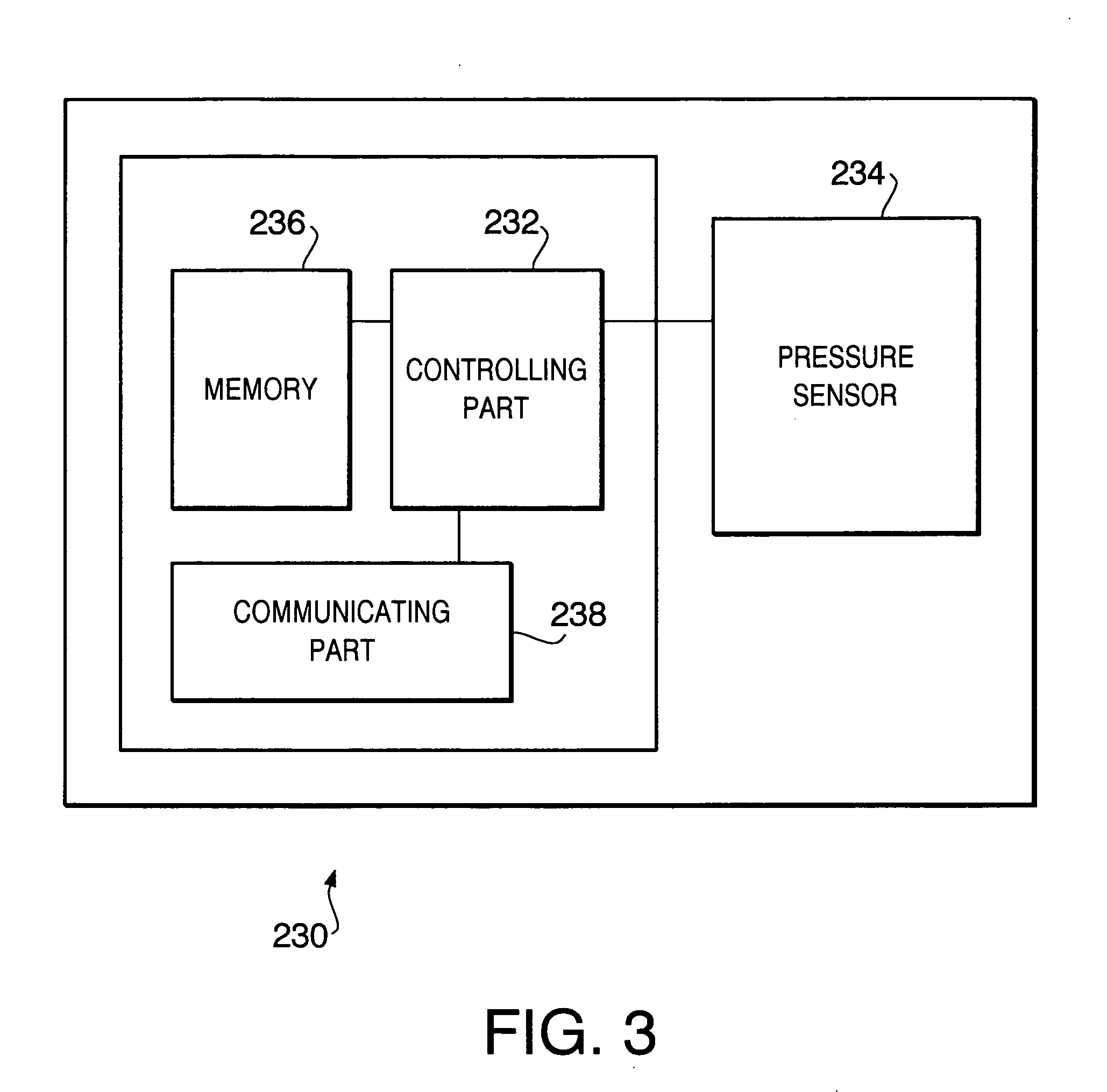
[0067] Next, a body pressure judging process that a controlling part 232 of a communication module 230 carries out in a second embodiment will be described.
[0068]FIG. 5 is a flowchart showing a body pressure judging process in a second embodiment. Hereinafter, the body pressure judging process of the second embodiment will be explained with reference to FIG. 5. It is noted that the below-mentioned explanation relates to a process that is carried out by the single communication module 230, in the same way as the above-mentioned body pressure judging process, but, needless to say, this body pressure judging process is performed by every communication module 230.
[0069] When the power supply of the control unit 220 is turned on, a driving voltage is supplied to the communication module 230, and the controlling part 232 first checks whether the driving voltage is supplied or not (that is, whether the power supply of the control unit 220 is off or not) (S21). In this step, when the power...
third embodiment
[0090] When a power switch of the control unit 220, which is not shown in any accompanying drawings, is turned on, the power supply 222 supplies electrical power to the control unit 220 to drive the control unit 220. The controlling part 221 is allowed to communicate with each of the communication modules 230 by using the aforementioned 2D-DST. In the third embodiment, each of the communication modules 230 acquires its own ID information by means of an algorithm stored in each of the controlling parts 232 to transmit the ID information to the control unit 220.
[0091] The controlling part 221 of the control unit 220 receives the ID information from each of the communication modules 230 (S51), and, based on the ID information, identifies each of the communication modules 230. In addition, the controlling part 221 has the ID information associated with the local addresses, and stores the body pressure value P detected by each of the communication modules 230 at a corresponding one of th...
PUM
 Abstract
Description
Claims
Application Information