Hand tool aided screwdriver

Inactive Publication Date: 2006-04-13
HU MICHAEL
View PDF12 Cites 1 Cited by
  • Summary
  • Abstract
  • Description
  • Claims
  • Application Information

AI Technical Summary

Benefits of technology

[0005] The primary purpose of the present invention is to provide a hand tool aided screwdriver to apply extra force on a work piece that requires greater torque. It saves efforts, allows one-way application of force, adaptable to socket with different recesses on both

Problems solved by technology

However, as the force applied is limited only to that from the wrist of t

Method used


Image

  • Hand tool aided screwdriver
  • Hand tool aided screwdriver
  • Hand tool aided screwdriver

Examples


Embodiment Construction

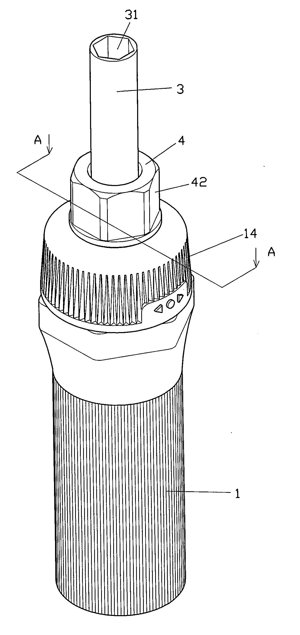
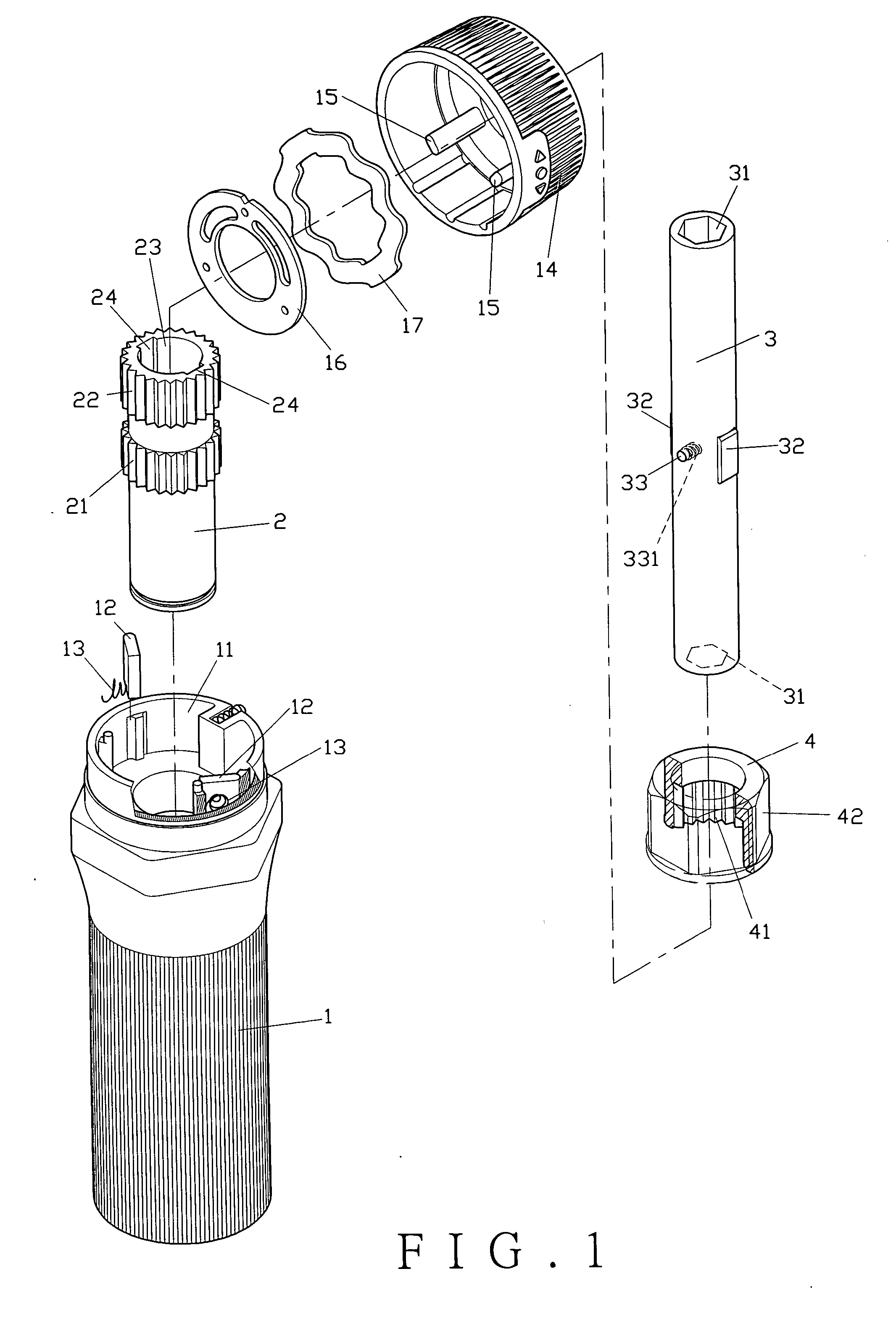
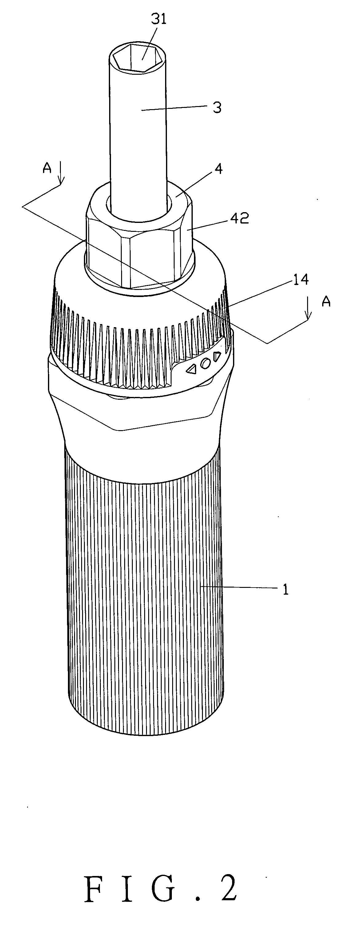
[0010] Referring to FIGS. 1, and 2, a preferred embodiment of the present invention comprises a handle (1), a ratchet holder (2), a socket (3), and a chock (4).

[0011] The handle (1) includes a chamber (11) containing two stoppers (12) each inserted with a spring (13). The chamber (11) is capped with a locking ring (14). The locking ring (14) contains two studs (15) to respectively hold against the stoppers (12) as the locking ring (14) is turned around. The locking ring (14) is inserted inside with a dust lid (16) and a gasket (17).

[0012] The ratchet holder (2) is secured into the chamber (11) of the handle (1). A ratchet (21) is provided on the middle section of the ratchet holder (2) to turn in one-way direction when held against by the stoppers (12). The top of the ratchet holder (2) exposes out of the locking ring (14) of the handle (1) and has on its outer circumference provided with an outer ratchet (22). A through hole (23) is provided in the ratchet holder (2). Two slots (...


PUM


Abstract

A hand tool aided screwdriver related to a ratchet screwdriver that allows operation in changed direction includes a handle, a ratchet holder, a socket, and a chock. The ratchet holder is inserted into a chamber in the handle. The socket is inserted into the ratchet holder. The ratchet holder is provided with an outer ratchet to engage with an inner ratchet in the chock. The chock having a hexagon outer surface to be held by an open end of a spanner to apply force together with the screwdriver in mounting or dismounting a work piece.

Description

BACKGROUND OF THE INVENTION [0001] (a) Field of the Invention [0002] The present invention relates to a hand tool aided screwdriver, and more particularly to a ratchet screwdriver allowing extra force to be jointly applied on a work piece from another hand tool such as a spanner by leverage. [0003] (b) Description of the Prior Art [0004] As taught in U.S. Pat. No. 6,260,446 for a ratchet screwdriver that permits application of extra force to drive a screw or a bolt in one direction or in a changed direction. However, as the force applied is limited only to that from the wrist of the user, more efforts are still needed for a job involving greater torque. SUMMARY OF THE INVENTION [0005] The primary purpose of the present invention is to provide a hand tool aided screwdriver to apply extra force on a work piece that requires greater torque. It saves efforts, allows one-way application of force, adaptable to socket with different recesses on both ends for connection with a screwdriver t...

Claims


Application Information

Patent Timeline
IPC IPC(8): B25B13/46
CPCB25B15/02B25B15/04
Inventor HU, MICHAEL
Owner HU MICHAEL
Why Eureka
Try Eureka