Circuit and method for controlling the rotating speed of a BLDC motor

Inactive Publication Date: 2008-09-11
GREEN MARK TECH
View PDF4 Cites 14 Cited by
  • Summary
  • Abstract
  • Description
  • Claims
  • Application Information

AI Technical Summary

Benefits of technology

[0012]Accordingly, the present invention is directed to a circuit for controlling the rotating speed of a BLDC motor, which solves the stall problem under sudden over-load

Problems solved by technology

One of the drawbacks of motor 204 in FIG. 2 is that, when the rotating speed is low and th

Method used


Image

  • Circuit and method for controlling the rotating speed of a BLDC motor
  • Circuit and method for controlling the rotating speed of a BLDC motor
  • Circuit and method for controlling the rotating speed of a BLDC motor

Examples


Embodiment Construction

[0025]Reference will now be made in detail to the present preferred embodiments of the invention, examples of which are illustrated in the accompanying drawings. Wherever possible, the same reference numbers are used in the drawings and the description to refer to the same or like parts.

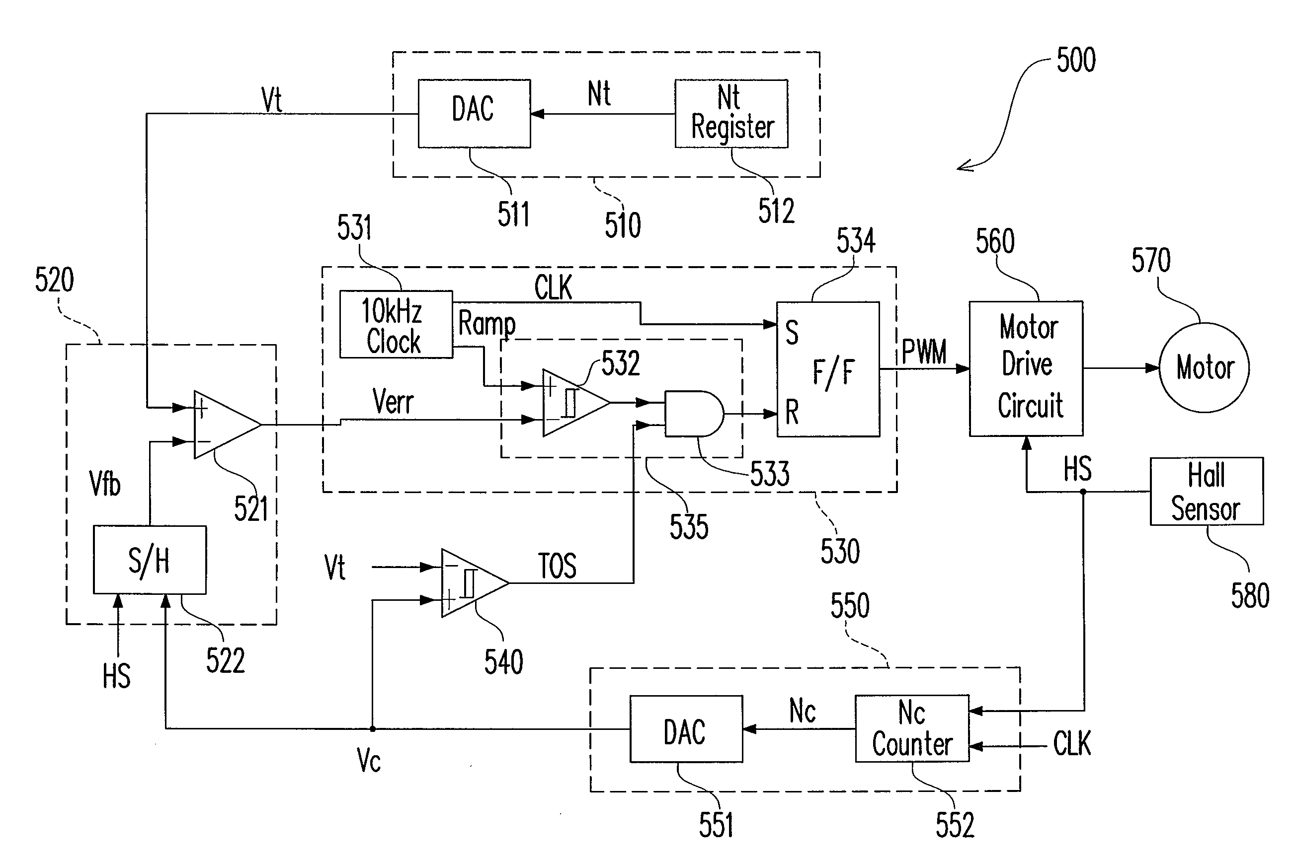
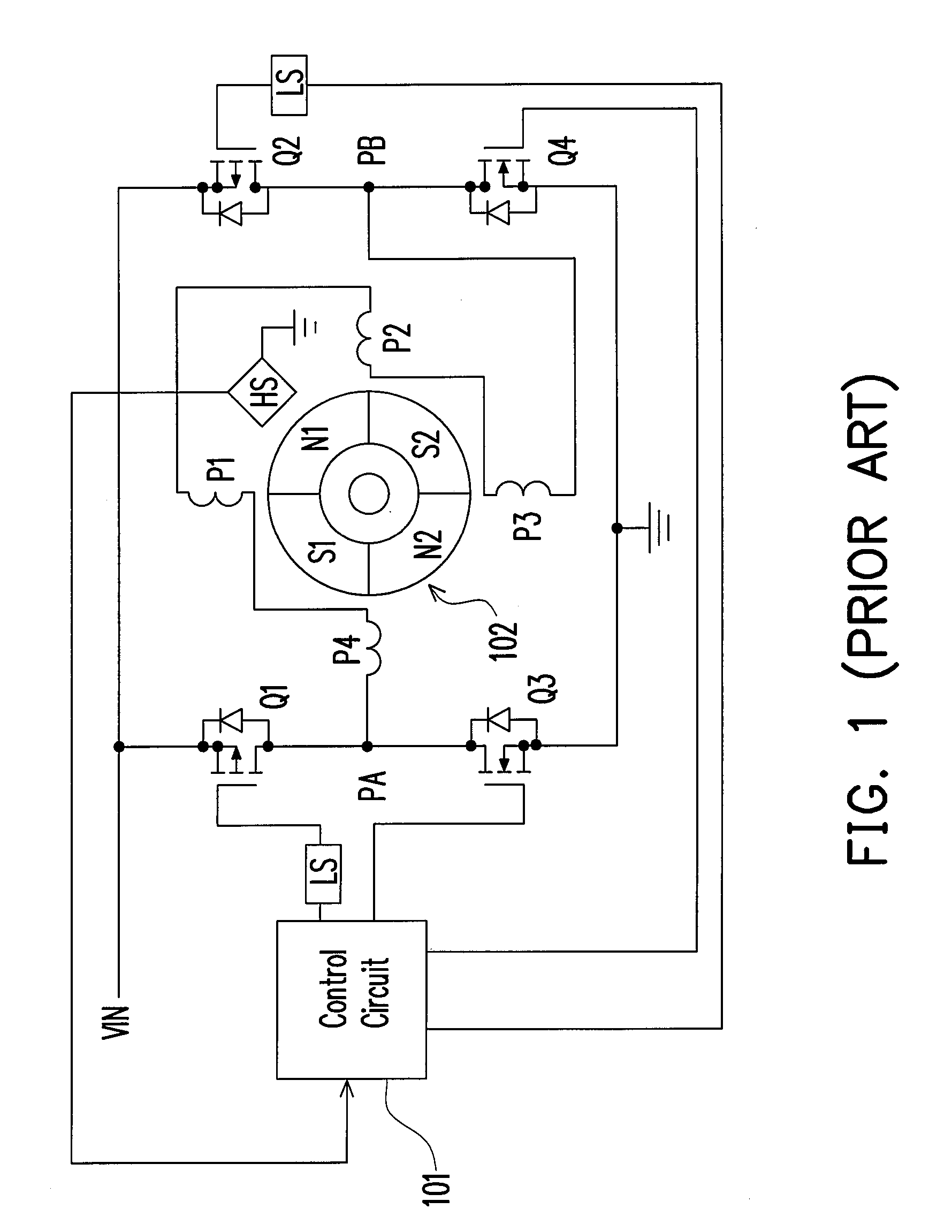
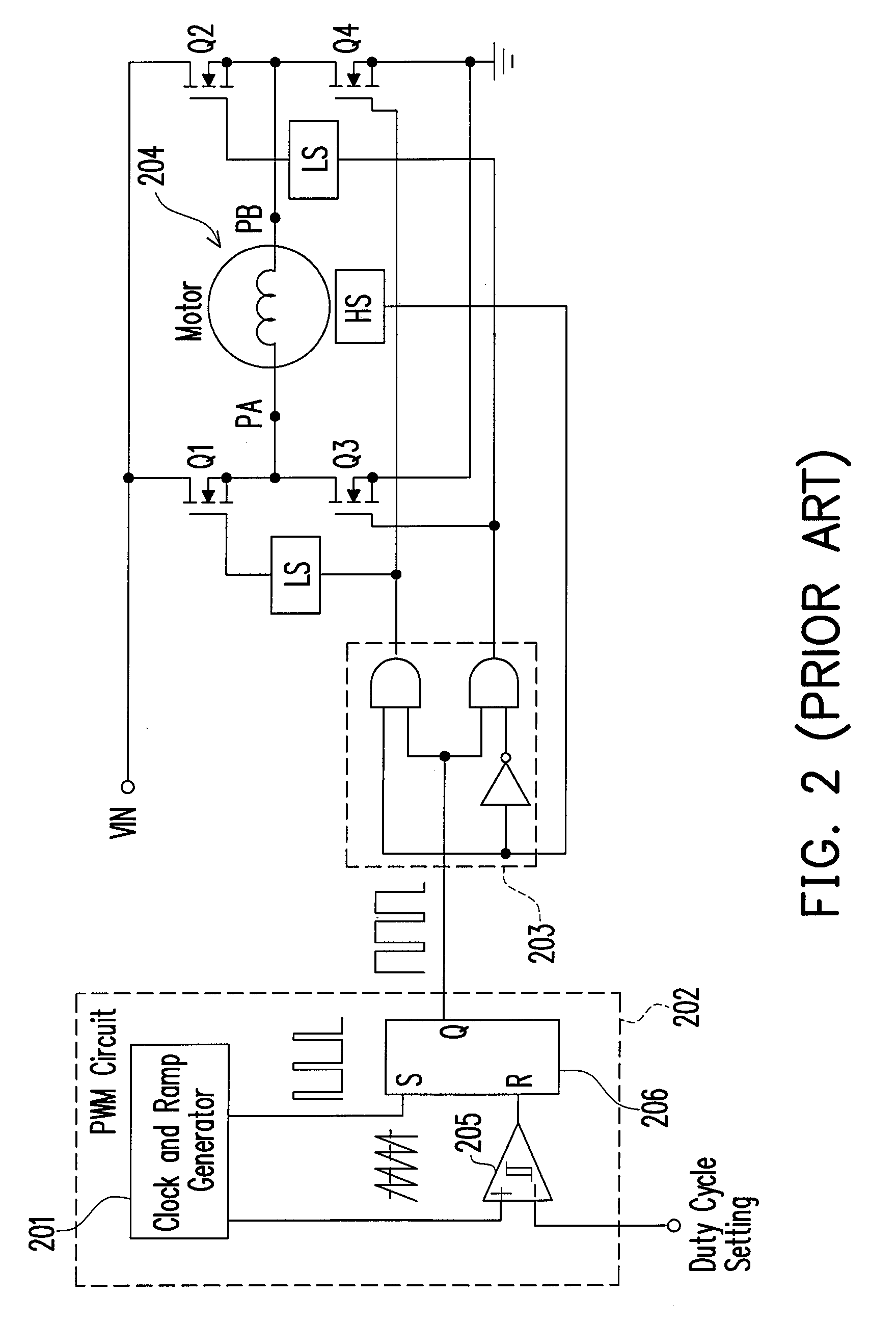
[0026]FIG. 4B shows the motor characteristic curves and the load characteristic curves according to an embodiment of the present invention. The dotted motor curves correspond to the conventional BLDC motor in FIG. 2. The solid motor curves 450, 452, 454 and 456 correspond to the BLDC motor in this embodiment. This embodiment is a circuit for controlling the rotating speed of the BLDC motor so that the rotating speed of the motor is always adjusted toward a predetermined target rotating speed no matter how the load condition changes. Unlike the conventional circuit in FIG. 2, in which the PWM signal has a constant duty cycle, this embodiment adjusts the duty cycle of the PWM signal according to the di...


PUM


Abstract

A circuit and a method for controlling the rotating speed of a brushless direct current (BLDC) motor are provided, whose goal is solving the stall problem encountered by conventional BLDC motors driven by pulse width modulation (PWM). The circuit includes a closed-loop control mechanism for adjusting the duty cycle of the motor current of the BLDC motor, thus controlling the rotating speed of the motor. The closed-loop control is based on the comparison of a signal proportional to the actual rotating speed and another signal proportional to the predetermined target rotating speed.

Description

BACKGROUND OF THE INVENTION[0001]1. Field of the Invention[0002]The present invention relates to a brushless direct current (BLDC) motor. More particularly, the present invention relates to a circuit and a method for controlling the rotating speed of a BLDC motor.[0003]2. Description of the Related Art[0004]FIG. 1 is a schematic diagram showing a conventional BLDC motor and its drive circuit. The BLDC motor includes a rotor 102 and stator coils P1-P4. Rotor 102 is a permanent magnet with two magnetic north poles (N1 and N2) and two magnetic south poles (S1 and S2). The position of Hall sensor HS is fixed relative to stator coils P1-P4. Hall sensor HS provides a Hall sensor signal whose state changes in response to the position of rotor 102 relative to stator P1-P4. In particular, the Hall sensor signal is high (logic 1) when N1 or N2 is the closer to Hall sensor HS among the magnetic poles, while the Hall sensor signal is low (logic 0) when S1 or S2 is the closer to Hall sensor HS a...

Claims


Application Information

Patent Timeline
IPC IPC(8): H02P7/29
CPCH02P6/16
Inventor LIU, KWANG-HWA
Owner GREEN MARK TECH
Why Eureka
Try Eureka