Axial-flow fan structure

Active Publication Date: 2006-01-03
DELTA ELECTRONICS INC
View PDF4 Cites 5 Cited by
  • Summary
  • Abstract
  • Description
  • Claims
  • Application Information

AI Technical Summary

Benefits of technology

[0008]The invention provides an improved axial-flow fan to efficiently use the air above the hub of the improved axial-flow fan.
[0009]It is therefore an object of the invention to provide an axial-flow fan structure with an improved hub, wherein the air above the hub may be guided sideways by the centrifugal force. Another object of the invention is to provide an axial-flow fan structure with an improved hub to solve the inherent stall problem of the conventional axial-flow fan and greatly enhance the fan efficiency. Thereby, the axial-flow fan structure in accordance with the invention can be applied in systems having higher system resistance.
[0012]In the axial-flow fan structure of the invention, since the air within the air intake space can be guided sideways by the centrifugal force when the fan rotates, the overall efficiency of the fan can be enhanced. Preferably, the lateral intake air flow effect can be enhanced when the distance from the top end of the fastening portion to the bottom boundary of the fan frame is smaller than three fourths of the height of the fan frame.
[0014]Summing up the above, since the fan according to the invention can effectively make use of the air above the hub during the rotation, the air flow and the static pressure can be increased. Furthermore, the stall effect of the fan during operation can be greatly decreased, thereby enhancing the overall efficiency of the fan. Also, because the height of the hub is reduced, the manufacturing cost of the fan can therefore be reduced, and the design of the fan can be simplified.

Problems solved by technology

However, the use of axial-flow fans is limited to systems with lower system resistance because the air flow output is restricted, and the stall problem occurs when the system resistance of an axial-flow fan gets larger.
On the other hand, since the boundary layer separation of air may occur on the blade surface when the rotating speed of the fan reaches a certain speed, the air flow cannot be increased even though the rotating speed of the fan is higher.
However, to solve the stall problem of axial-flow fans, the focus has always been on the design of angles, lengths, and number of the blades; and yet no simple and effective solutions have been found for the problem.

Method used


Image

  • Axial-flow fan structure
  • Axial-flow fan structure
  • Axial-flow fan structure

Examples


Embodiment Construction

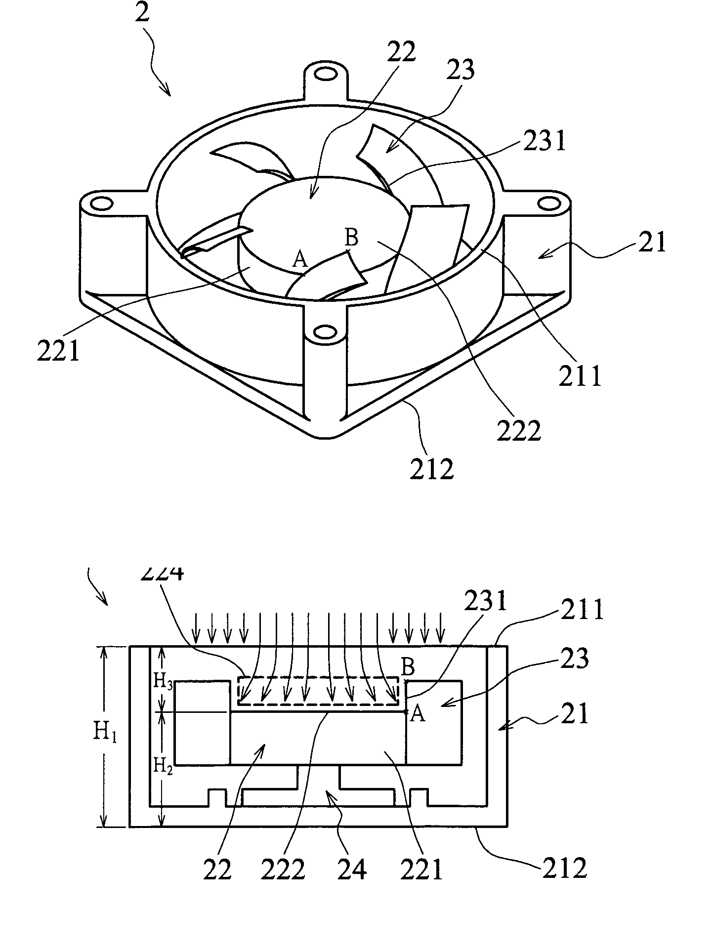
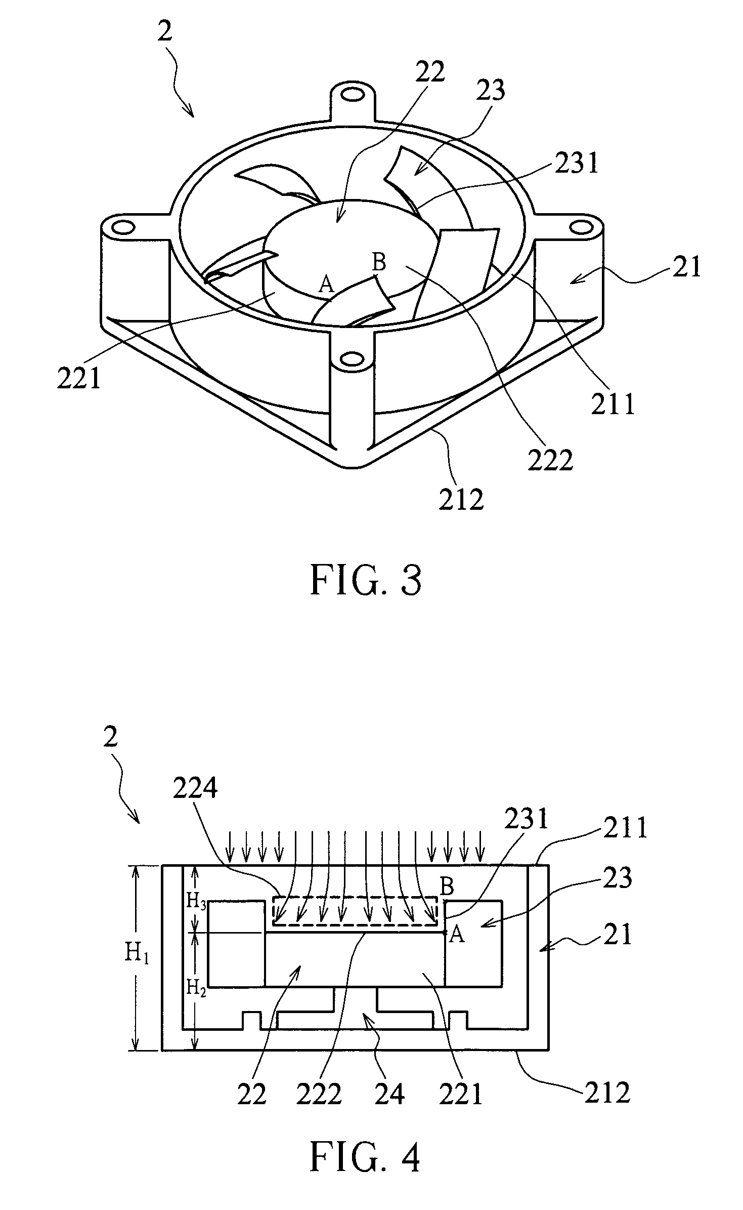
[0022]Referring to FIGS. 3 and 4, the axial-flow fan 2 in accordance with one embodiment of the invention includes a fan frame 21, a cylindrical hub 22, a plurality of blades 23 fastened to a side surface 221 of the hub 22 and aligned around the hub 22, and a stator base 24. The fan frame 21 has a top boundary 211 and a bottom boundary 212 and is for receiving the cylindrical hub 22 and the blades 23. Moreover, a top end A of a fastening portion, between a side surface 221 of the hub 22 and an edge portion 231 of each blade 23 of the axial-flow fan 2, is lower than a top end B of an edge portion 231 of each blade. Accordingly, the region 224 surrounded by all the edge portions 231 of the blades 23 is formed between the top boundary 211 of the fan frame 21 and the top surface 222 of the hub 22 and serves as a lateral air intake region. In addition, the surrounding surface formed by the inner surfaces of all the edge portions 231 serves as a lateral air intake surface to guide air wit...


PUM


Abstract

An improved axial-flow fan structure is disclosed and claimed, which includes a hub and a plurality of blades. The hub has a top surface and a side surface around which the plurality of blades is mounted. A lateral air intake region is formed above the top surface of the hub and surrounded by edge portions of all of the blades. A lateral air intake surface around the lateral air intake region is constituted by the edge portions of all of the blades. A part of each of the edge portions is fastened to the side surface of the hub.

Description

BACKGROUND OF THE INVENTION[0001]1. Field of the Invention[0002]The invention relates to a fan structure and, more particularly, to an axial-flow fan structure capable of directing an air flow sideways.[0003]2. Description of the Related Art[0004]A fan is used to direct air to flow and thus to dissipate heat, and better air directing efficiency results in better heat dissipating efficiency. Usually, there are two types of fans; namely, axial-flow fans and centrifugal fans. In an axial-flow fan, an impeller is rotated to direct an air flow in a direction parallel to the central axis of the impeller. Having advantages of simple structures, lower manufacturing costs, and higher air flow output, axial-flow fans are widely used in air conditioners and heat dissipating devices such as heat-dissipating fans in computer systems. However, the use of axial-flow fans is limited to systems with lower system resistance because the air flow output is restricted, and the stall problem occurs when ...

Claims


Application Information

Patent Timeline
IPC IPC(8): F04D29/24F04D29/44F04D25/08F04D29/32F04D29/38F04D29/54H05K7/20
CPCF04D29/325H05K7/20172F04D29/384
Inventor CHIU, YUNG-YUCHANG, SHUN-CHENLIN, KUO-CHENG
Owner DELTA ELECTRONICS INC
Why Eureka
Try Eureka