Fan and electronic device equipped with the same

a technology of electronic devices and fan blades, which is applied in the direction of ventilation systems, electrical apparatus casings/cabinets/drawers, instruments, etc., can solve the problems of difficult resin molding, high cost, and undercutting between the blades, so as to reduce the exhaust flow, the effect of greatly increasing the static pressur

Inactive Publication Date: 2013-08-13
PANASONIC CORP
View PDF45 Cites 11 Cited by
  • Summary
  • Abstract
  • Description
  • Claims
  • Application Information

AI Technical Summary

Benefits of technology

[0028]Further, in the fan of Japanese Unexamined Patent Application No. H05-044697, a certain level of exhaust flow can be secured, even in the area in which the suction distance h3 is small. However, since the shape of the hub to which the blades are attached is a circular cone, in the case that the blades and hub are integrally resin molded using one group of dies having a simple constitution, an undercut may occur between the blades and the hub. Therefore, in the fan of Japanese Unexamined Patent Application No. H05-044697, there are issues in that resin molding is difficult, and it is necessary to attach the blades to the hub as separate members, and thus the cost becomes high.
[0072]According to the fan of the present invention, since a gap between the blades and the air duct is constituted to be bigger than a gap of the air flow guiding plate, by the propeller-shaped blades, in addition to an air flow which is pushed out in the rotation axis direction, an air flow which is pushed out in the centrifugal direction can be created in the gap between the blades and the air duct. Thereby, the static pressure can be greatly increased compared to conventional fans. Further, even in the case that obstructions such as a chassis, parts, and boards within the electronic device are disposed near the portion of the fan on the suction side, a reduction in exhaust flow can be suppressed, and the necessary exhaust flow amount can be secured. In addition, since the exhaust outlet and the suction inlet are formed such that the rotation axis passes through their insides, i.e. since the exhaust outlet and the suction inlet are in a front-rear relationship, air which is sucked in from the suction inlet can be discharged to the exhaust outlet on the rear side.

Problems solved by technology

However, since the shape of the hub to which the blades are attached is a circular cone, in the case that the blades and hub are integrally resin molded using one group of dies having a simple constitution, an undercut may occur between the blades and the hub.
H05-044697, there are issues in that resin molding is difficult, and it is necessary to attach the blades to the hub as separate members, and thus the cost becomes high.
Therefore, an issue arises in that, in the case that this fan is used in an electronic device in which the ventilation resistance is not so large, such a fan is not necessarily effective.

Method used


Image

  • Fan and electronic device equipped with the same
  • Fan and electronic device equipped with the same
  • Fan and electronic device equipped with the same

Examples


first embodiment

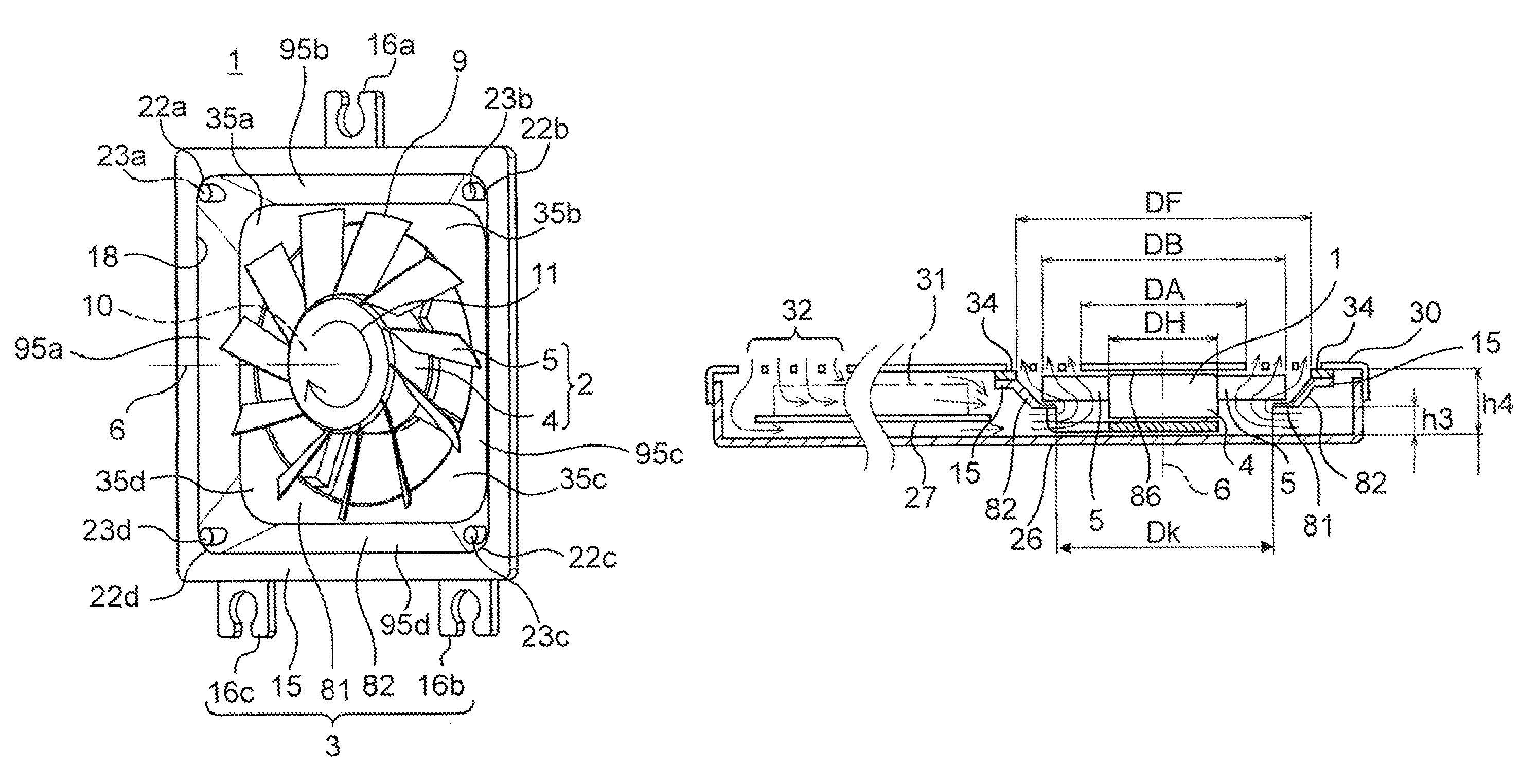
[0139]The fan according to a first embodiment of the present invention and an electronic device equipped with this fan will be explained using FIGS. 1A to 12.

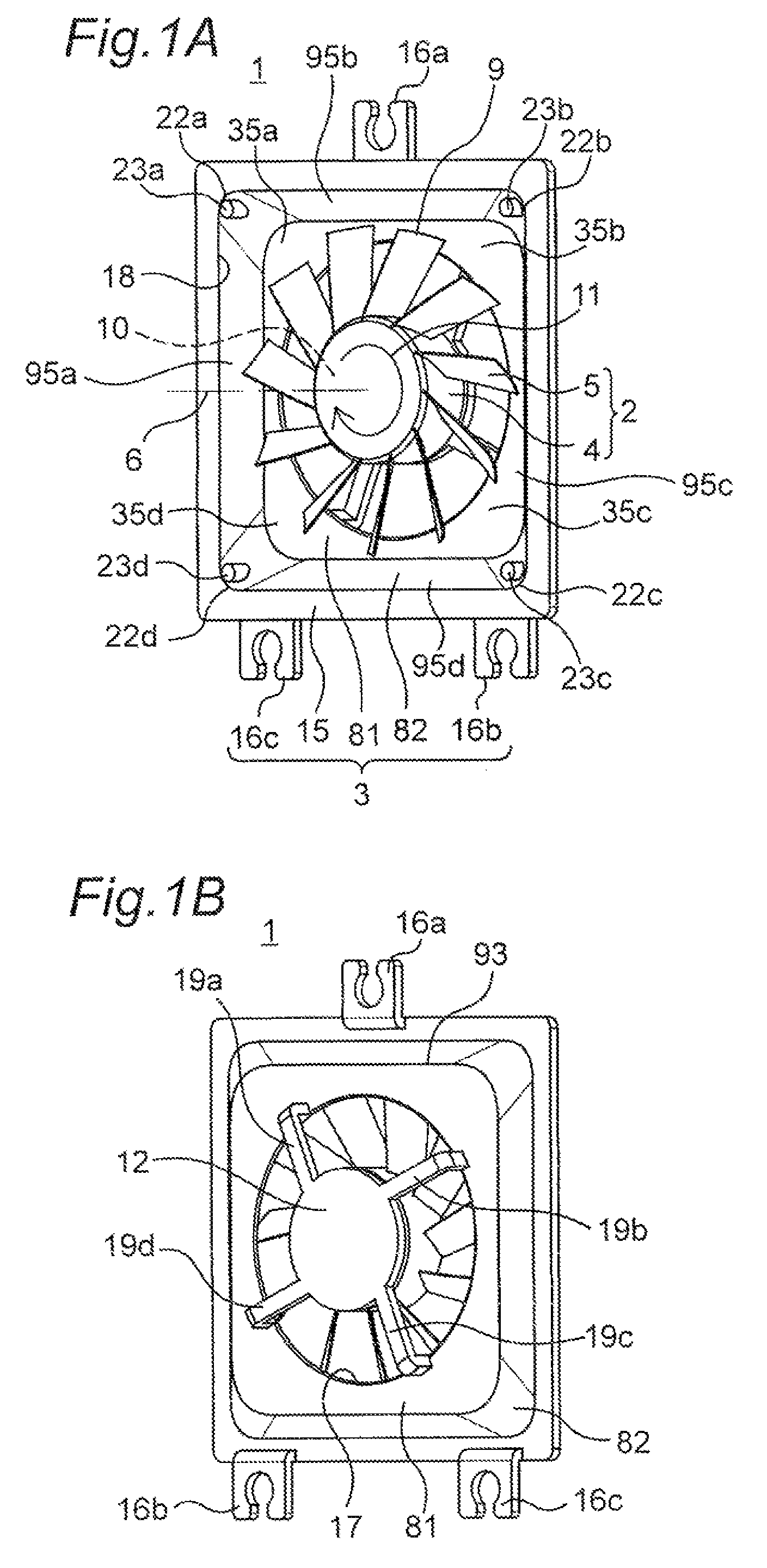
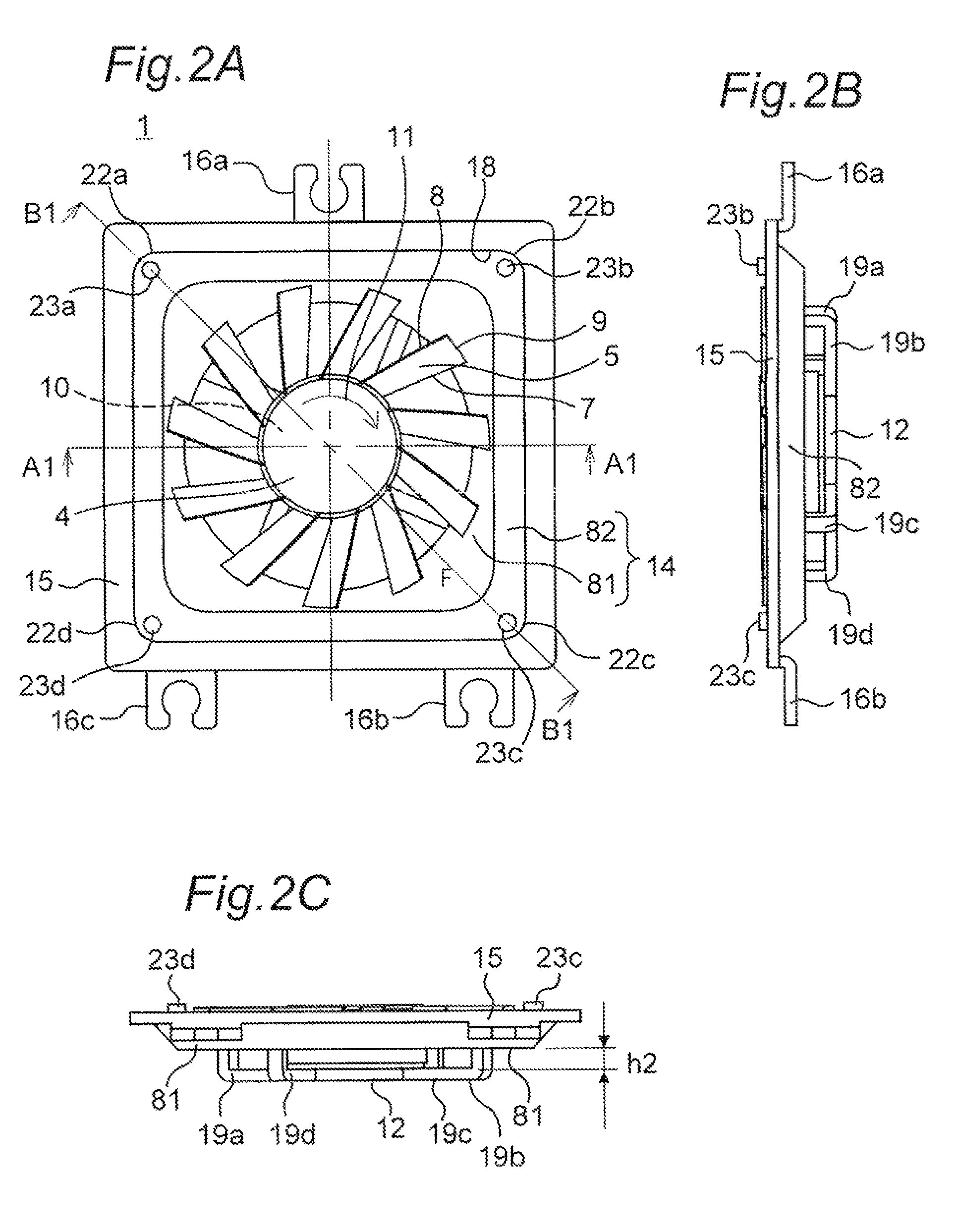
[0140]FIG. 1A is a perspective view of the fan according to the first embodiment of the present invention when viewed from the exhaust side, and FIG. 1B is a perspective view of the fan when viewed from the suction side. FIG. 2A is a plan view of the fan according to the first embodiment of the present invention when viewed from the exhaust side; FIG. 2B is a right-side surface view of the fan shown in FIG. 2A; FIG. 2C is a bottom-side surface view of the fan shown in FIG. 2A; FIG. 2D is a partial cross-section view taken along line A1-A1 of the fan shown in FIG. 2A; FIG. 2E is a partially enlarged cross-section view of FIG. 2D; and FIG. 2F is a partial cross-section view taken along line B1-B1 of the fan shown in FIG. 2A. The outline of the blade 5 shown in FIGS. 2D, 2E, and 2F shows a rotation trajectory when the blade 5 is r...

second embodiment

[0203]Next, the constitution of the fan according to a second embodiment of the present invention will be explained using FIGS. 13A to 16B. FIG. 13A is a perspective view of the fan according to the second embodiment of the present invention when viewed from the exhaust side, and FIG. 13B is a perspective view of the fan shown in FIG. 13 A when viewed from the suction side. FIG. 14A is a plan view of the fan according to the second embodiment of the present invention when viewed from the exhaust side, and FIG. 14B is a plan view of the fan shown in FIG. 14A when viewed from the suction side. FIG. 14C is a bottom-side surface view of the fan shown in FIG. 14A. FIG. 14D is a partial cross-section view taken along line A5-A5 of the fan shown in FIG. 14A, and FIG. 14E is a partial cross-section view taken along line B5-B5 of the fan shown in FIG. 14A. FIG. 14F is a partially enlarged cross-section view of FIG. 14E. The outline of the blade 5 shown in FIGS. 14D and 14E shows the rotation...

third embodiment

[0219]Next, the constitution of the fan according to a third embodiment of the present invention will be explained using FIG. 17.

[0220]FIG. 17A is a plan view of a fan 1y according to a third embodiment of the present invention when viewed from the exhaust side. FIG. 17B is a partial cross-section view taken along line A6-A6 of the fan 1y shown in FIG. 17A. The outline of the blade 5x shown in FIG. 17B shows the rotation trajectory when the blade 5x is rotating. FIG. 18 is a partial cross-section view of an electronic device in which the fan 1y shown in FIG. 17A is mounted.

[0221]A fan 1y according to the third embodiment of the present invention differs from the fan 1x according to the second embodiment in that a disc 90 is newly provided. The fans are the same with respect to all other points, and the constitution of the fan 1y according to the third embodiment will be explained below while omitting any duplicate explanations.

[0222]The disc 90 is fixed to a portion of the blade 5x ...


PUM


Abstract

A fan includes, an impeller having propeller-shaped blades, a motor disposed inside of a hub to rotationally drive the impeller centered on the rotation axis, a tubular air duct forming an air passage on a periphery of the blades of the impeller and the rotation axis, wherein the rotation axis penetrates the inside of the air duct, and an exhaust outlet larger than an outer diameter of a rotation trajectory of the blades is formed on one end of the air duct, and an air flow guiding plate blocking an opening on an other end of the air duct in the rotation axis direction, a suction inlet through which the rotation axis passes being formed in approximately the center of the air flow guiding plate, wherein the blades are closer to the air flow guiding plate than the air duct.

Description

BACKGROUND OF THE INVENTION[0001]I. Technical Field[0002]The present invention is related to a fan which is disposed within a casing of an electronic device and discharges air within the casing to an outside of the casing, and also related to an electronic device in which the fan is mounted.[0003]II. Description of the Related Art[0004]Among various electronic devices, in those devices in which the amount of heat release within the device is large, a fan which discharges air within the device to the outside is generally mounted for cooling the inside. The majority of such fans are disposed near an inner surface of an outer wall of the electronic device in parallel with the inner surface. In recent years, many electronic devices equipped with a fan have been miniaturized or are thinner. Therefore, the space in which the fan is disposed has also become smaller. In other words, a gap between a portion of the fan on the suction side and parts, circuit boards, chassis, and the like mount...

Claims


Application Information

Patent Timeline
Patent Type & Authority Patents(United States)
IPC IPC(8): H05K7/20F04D29/54
CPCF04D25/08F04D25/12F04D29/542F04D29/601F04D25/0613F04D29/544
Inventor TAKAHASI, KAZUYUKIKOUJITANI, TSUTOMUKAWASHIMA, SYOUJI
Owner PANASONIC CORP
Why Eureka
Try Eureka