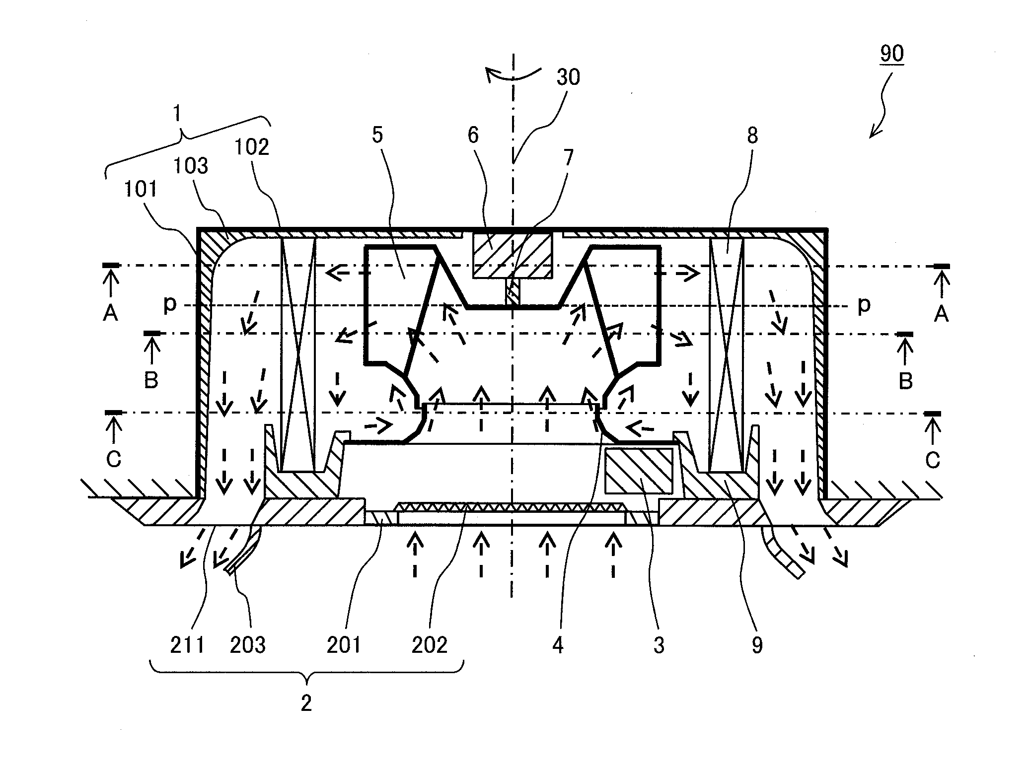
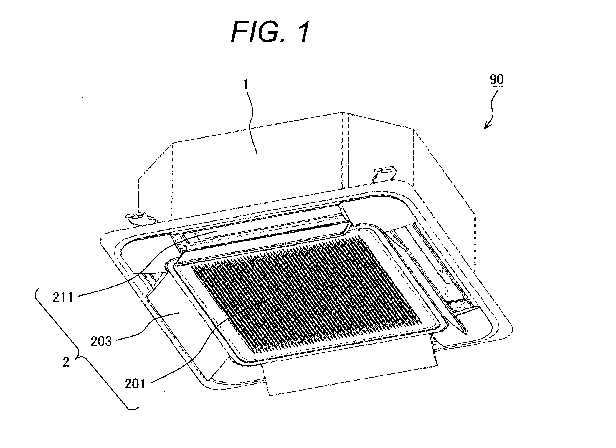
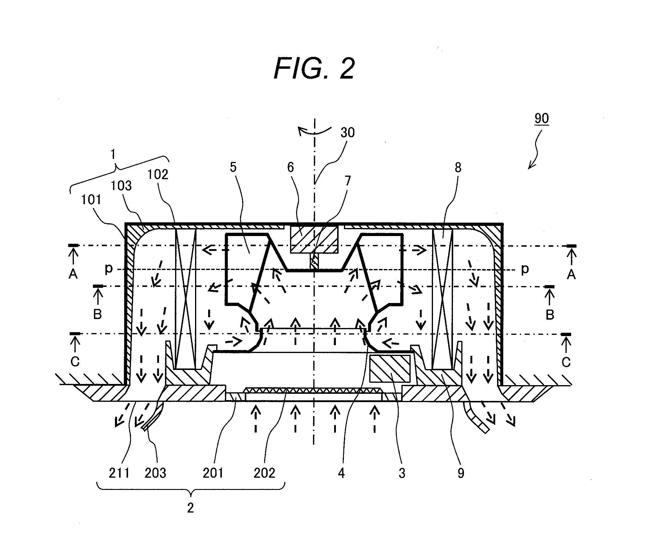
Air Conditioning Unit

a technology for air conditioning and air conditioners, applied in space heating and ventilation, lighting and heating apparatuses, heating types, etc., can solve the problems of deterioration of heat exchange performance, increased blower power, turbulence in flow, etc., to achieve lessen the improvement effect, increase the static pressure of air, and easily cause turbulence in flow

Inactive Publication Date: 2016-08-04
HITACHI JOHNSON CONTROLS AIR CONDITIONING INC
View PDF5 Cites 10 Cited by
  • Summary
  • Abstract
  • Description
  • Claims
  • Application Information

AI Technical Summary

Benefits of technology

[0013]In the generally employed structure disclosed in Patent Document 3, an angle formed by the rectifying plate and the air inflow surface continuously varies in a fan rotation axial direction. However, an air flow direction exhibits a steep change in the fan rotation axial direction in accordance with a shape of a centrifugal fan blade, and a positional relationship with an air outlet. In this case, a part of the rectifying plate may have its direction largely deviated from the air flow direction. As a result, the flow separates from a surface of the rectifying plate, resulting in a lessened improvement effect. Meanwhile, the rectifying plate with the stepped shape causes a steep change in a distance between the rectifying plate and the air inflow surface around a stepped section. This may easily cause turbulence in the flow.
[0014]An object of the present invention provides an air conditioning unit which has an indoor unit including a centrifugal fan, the indoor unit being configured to increase a static pressure of air both at an upstream side and a downstream side of a vane of a rectifying member (a rectifying plate) so as to realize a reduction in a blower power and an improvement in a heat exchanging performance.
[0015]The present invention provides an air conditioning unit having an indoor unit, the indoor unit including: a casing; a centrifugal fan having a hub, a shroud, and blades disposed therebetween; and an indoor heat exchanger which surrounds the centrifugal fan, the casing containing the centrifugal fan and the indoor heat exchanger. In the indoor unit, the indoor heat exchanger has a planar air inflow surface allowing an inflow of air discharged from an air outlet of the centrifugal fan, the air inflow surface is provided with a rectifying member, the rectifying member includes a support having an insertion portion fixed between fins on the air inflow surface, and a vane having a shape extending from the support toward a direction opposite a rotating direction of the centrifugal fan, the rectifying member configured to block some of the air flowing between the centrifugal fan and the air inflow surface, and an angle formed by the insertion portion and the vane in the plane orthogonal to a rotation axis of the centrifugal fan is set to become parallel to the air inflow from the air outlet to the air inflow surface at least at the hub side to increase a static pressure of the air at upstream and downstream sides of the vane.
[0016]According to the present invention, in the indoor unit including the centrifugal fan for the air conditioning unit, it is possible to increase an air static pressure both at the upstream and downstream sides of the vane of the rectifying member (rectifying plate). This makes it possible to realize a reduced blower power and an improved heat exchanging performance, resulting in a highly efficient air conditioning unit.

Problems solved by technology

However, the aforementioned structure may generate a region behind the rectifying plate where an air flow velocity is significantly decreased, leading to a deteriorated heat exchanging performance and an increased blower power.
This may easily cause turbulence in the flow.

Method used


Image

  • Air Conditioning Unit
  • Air Conditioning Unit
  • Air Conditioning Unit

Examples


first embodiment

[0060]A first embodiment of the present invention will be described referring to FIGS. 8 to 11. FIG. 8 is a longitudinal section of an indoor unit 91 including the fan rotation axis. FIG. 9 is a transverse section of the indoor unit 91 taken along line D-D of FIG. 8. FIG. 10 is an enlarged perspective view of a rectifying member 920. FIG. 11 is a bottom view of the rectifying member 920 seen from a direction indicated by arrow Z of FIG. 10. In the drawings, the lines s-s, p-p, q-q, and t-t indicate a position of the hub of the centrifugal fan 5, the inflection point position at which the blade rear edge changes its shape from convex to concave, an upper end position of the shroud, and a lower end position of the shroud, respectively. Numeral 811 denotes an air inflow surface of the heat exchanger 8.

[0061]The rectifying member 920 includes a thin plate support 931, a thin plate vane 932 which extends from one end of the support 931 toward a direction opposite a fan rotating direction...

second embodiment

[0088]In this embodiment, the same components as those described in the first embodiment will be designated with the same numerals, and explanations thereof, thus will be omitted so that the difference from the first embodiment will be explained mainly hereinafter.

[0089]FIG. 13 represents the second embodiment according to the present invention. The support 931 of a rectifying member 921 has rectangular openings 941, 942 through which the inflow air between the vane and the air inflow surface 811 of the heat exchanger partially flows to the rear of the support 931. Therefore, even if the vane direction is deviated from the given direction owing to a fitting error, it is possible to suppress the region where the flow velocity is significantly lowered. Adjustment of the number of openings, size and position thereof allows control of the static pressure improvement effect in the fan rotation axial direction.

third embodiment

[0090]FIG. 14 represents a third embodiment according to the present invention. This embodiment is different from the first embodiment in that the support 931 has an extended thin plate section 951 at the lower end. Some of the flowing air around the air inflow surface 811 is blocked in the region below the centrifugal fan 5 so that the amount of air passing through the part of the heat exchanger at an anterior position of a fitted position of the thin plate section 951 increases together with the static pressure. Meanwhile, the part of the thin plate section 951 protruding from the air inflow surface 811 is very low in height. This makes it possible to suppress reduction in the flow velocity behind the part. As a result, the improvement effect of the rectifying member may further be enhanced.


PUM


Abstract

The present invention provides an air conditioning unit having an indoor unit, the indoor unit including: a casing; a centrifugal fan having a hub, a shroud, and blades disposed therebetween; and an indoor heat exchanger which surrounds the centrifugal fan, the casing containing the centrifugal fan and the indoor heat exchanger. In the indoor unit, the indoor heat exchanger has a planar air inflow surface allowing an inflow of air discharged from an air outlet of the centrifugal fan, the air inflow surface is provided with a rectifying member, the rectifying member includes a support having an insertion portion fixed between fins on the air inflow surface, and a vane having a shape extending from the support toward a direction opposite a rotating direction of the centrifugal fan, the rectifying member configured to block some of the air flowing between the centrifugal fan and the air inflow surface, and an angle formed by the insertion portion and the vane in the plane orthogonal to a rotation axis of the centrifugal fan is set to become parallel to the air inflow from the air outlet to the air inflow surface at least at the hub side to increase a static pressure of the air at upstream and downstream sides of the vane.

Description

CLAIM OF PRIORITY[0001]The present application claims priority from Japanese Patent application serial No. 2015-017048, filed on Jan. 30, 2015, the content of which is hereby incorporated by reference into this application.BACKGROUND OF THE INVENTION[0002]1. Field of the Invention[0003]The present invention relates to an air conditioning unit.[0004]2. Description of Related Art[0005]An air conditioning unit includes an indoor unit, an outdoor unit, and a piping for connecting the indoor unit and the outdoor unit. There are various types of indoor units including a ceiling embedded cassette type.[0006]The ceiling embedded cassette type indoor unit generally includes a centrifugal fan which takes in air from a rotation axial direction and discharges the air from an outer periphery portion, and a heat exchanger with a polygonal shape for externally surrounding the centrifugal fan.[0007]The above-described structure is configured that the air discharged from the centrifugal fan is obliq...

Claims


Application Information

Patent Timeline
Patent Type & Authority Applications(United States)
IPC IPC(8): F24F1/00F24F13/24
CPCF24F1/0022F24F2001/0037F24F13/24F24F13/08F24F13/30F24F2013/0616F24F1/0047
Inventor XUE, JUNSATOH, DAIWAOBARA, HIDESHIFUSHIMI, NAOYUKIIWASE, TAKUTSUCHIHASHI, KAZUHIRO
Owner HITACHI JOHNSON CONTROLS AIR CONDITIONING INC
Why Eureka
Try Eureka