Fuel injection valve for internal combustion engines

a technology for internal combustion engines and fuel injection valves, which is applied to engine components, spray nozzles, liquid spraying apparatus, etc., can solve the problem of cost of manufacturing control elements, and achieve the effect of preventing uncontrolled adjustment of valve elements, reducing the loss of energy resulting from pressure reduction in the control chamber, and facilitating manufacturing

Inactive Publication Date: 2006-02-07
CRT COMMON RAIL TECH
View PDF11 Cites 11 Cited by
  • Summary
  • Abstract
  • Description
  • Claims
  • Application Information

AI Technical Summary

Benefits of technology

[0009]Since the control chamber is thus directly connected via the throttle inlet to the high pressure chamber in which the fuel system pressure is present, without passing through an intermediate throttle point, the static pressure in the control chamber is higher than in the known fuel injection valve which is described above. The result of this is that the delay time between the closing of the one end of the control passage by the pilot valve and the closing of the injection openings by the injection valve element is shortened and in addition uncontrolled adjustment of the valve element is prevented. In addition, the quantity of fuel which flows into the control chamber through the throttle inlet during an injection process can be kept small. As a result, the loss of energy resulting from a pressure reduction in the control chamber can be minimized whenever the control passage is cleared.
[0010]Owing to the smaller number of passages and bores, the control element is easier to manufacture than in the case of the above mentioned, known fuel injection valve.

Problems solved by technology

The known fuel injection valve has, inter alia, the disadvantage that it is costly to manufacture the control element.

Method used


Image

  • Fuel injection valve for internal combustion engines
  • Fuel injection valve for internal combustion engines
  • Fuel injection valve for internal combustion engines

Examples


first embodiment

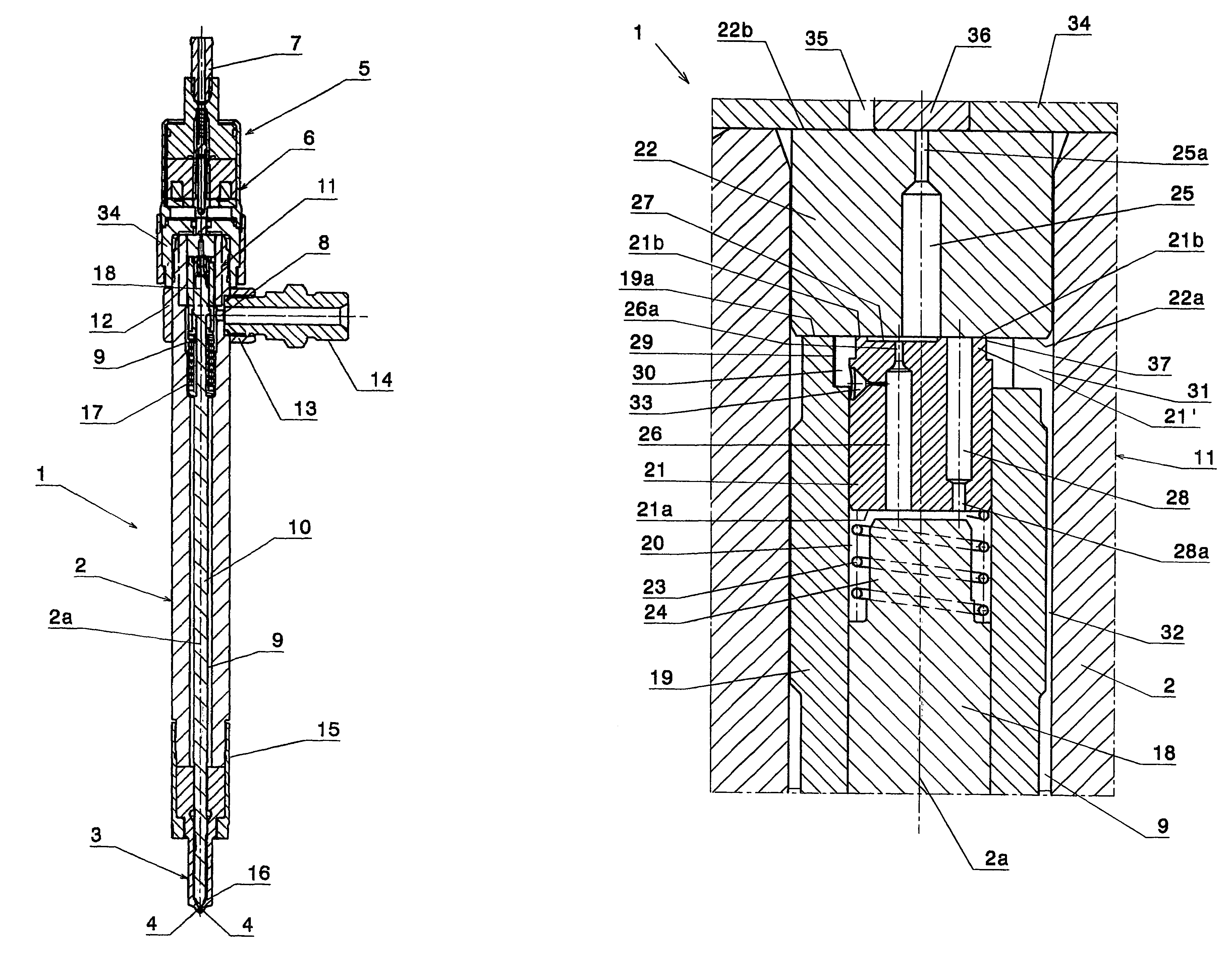
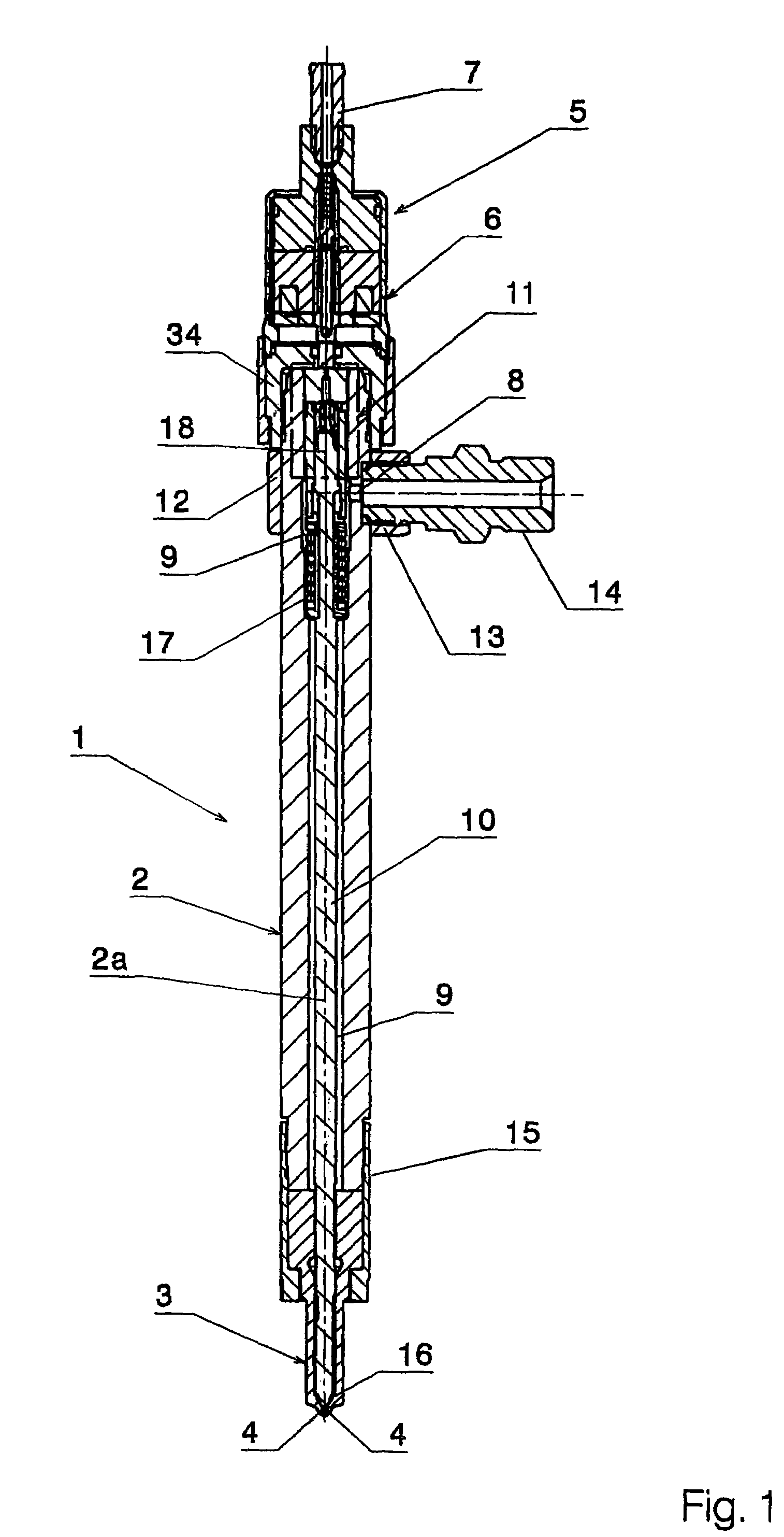
[0017]FIG. 1 shows an axial section through a fuel injection valve 1 according to the invention. The latter has a tubular, elongate housing 2 whose longitudinal axis is designated by 2a. A valve seat element 3 with injection openings 4 is attached to the housing 2 at one end, and a pilot valve 5 which can be activated electromagnetically is attached to the other end. The pilot valve 5, which is of a configuration which is known per se, has an electromagnet 6. The fuel injection valve 1 is also provided with a low pressure outlet connector 7 to which a return line (not shown), which feeds fuel into a fuel reservoir (also not shown), is connected.

[0018]The housing 2 is provided with a bore which serves as a high pressure inlet 8 and extends in the radial direction and through which fuel is introduced, at a high pressure (200 to 2000 bar or more), into a high pressure chamber 9 which is formed in the interior of the housing 2. The high pressure chamber 9 extends in the axial direction ...

second embodiment

[0035]the control device 11 will now be described with reference to FIG. 4. Moreover, the fuel injection valve 1 is of identical design, as is shown by FIGS. 1 and 2. For identical and identically acting parts, the same reference symbols are used in FIG. 4 as in FIGS. 1 and 2.

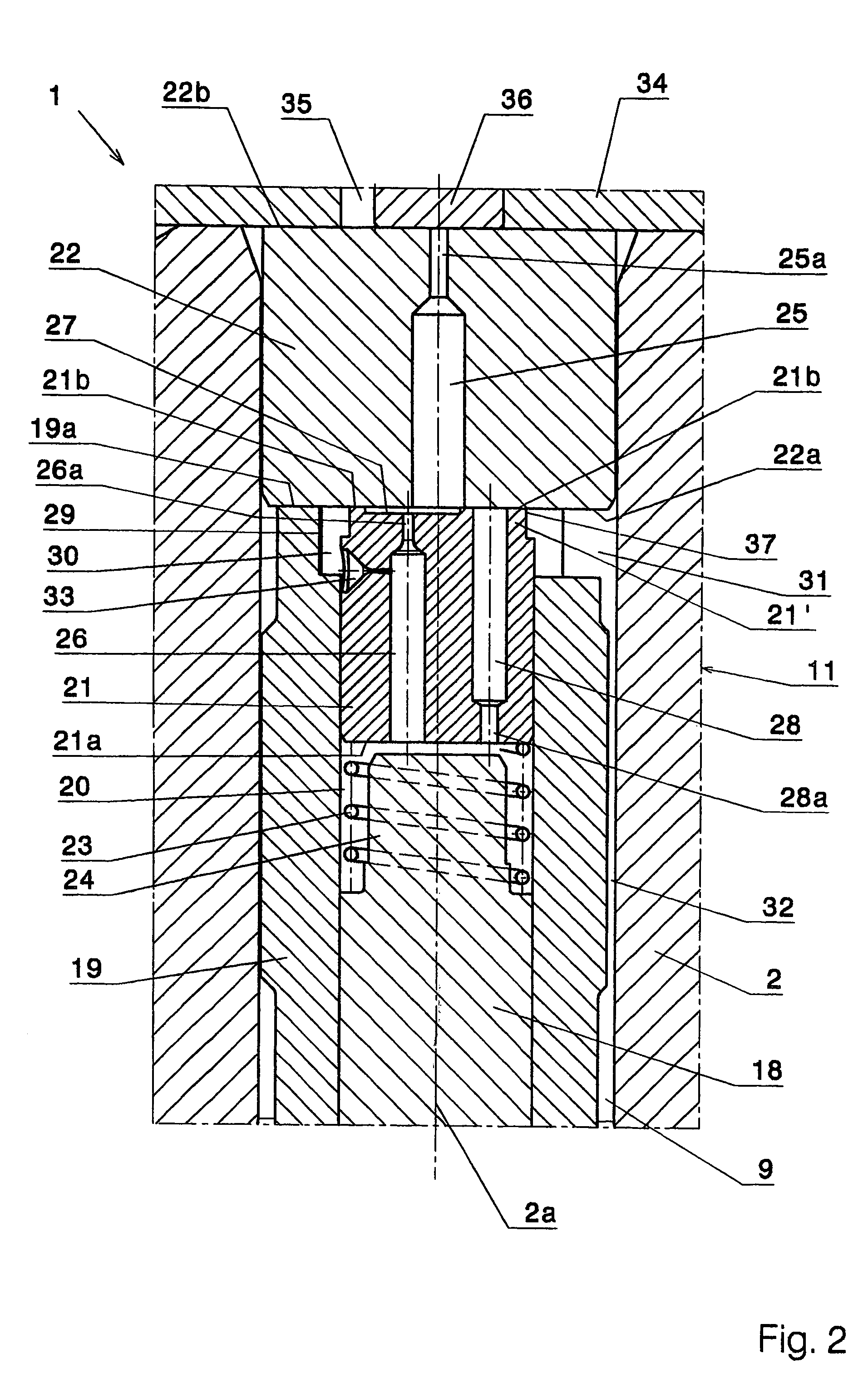
[0036]The embodiment which is shown in FIG. 4 also has a tubular housing 2 in which the control element 22 is arranged in a firmly seated fashion. The sleeve 19, in which the double-acting control piston 18 of the injection valve element 10 is arranged with a tight fit and so as to be moveable in the axial direction, is supported, by its end side 19a facing the control chamber 20, on the control element 22 in a seal-forming fashion. The control chamber 20 is thus bounded at one end by the control piston 18, around the circumference by the sleeve 19 and at the other end by the control element 22. The throttle inlet 33, which is formed in the sleeve 19 and is connected to the high pressure chamber 9 via the flow ...

third embodiment

[0043]the control device 11 will be described with reference to FIG. 5. Moreover, the fuel injection valve 1 is identical to the design shown in FIGS. 1 and 2. The same reference symbols as in FIGS. 1 and 2 are used for FIG. 5 for identical and identically acting parts.

[0044]The embodiment shown in FIG. 5 also has a tubular housing 2 in which the control element 22 is arranged fixed to the housing. At its end facing the control element 22, the sleeve 19, in which the double-acting control piston 18 of the injection valve element 10 is arranged with a tight fit so as to be moveable in the axial direction, is supported on the control element 22. For this purpose, the sleeve 18 is provided with an annular shoulder 44, in which a guide part 22′, guiding the sleeve 19, of the control element 22 engages. It is also conceivable to guide the sleeve 19 by means of a guide which is arranged in the flow gap 32 and is provided with passages. In this case, the annular shoulder 44 is dispensed wi...


PUM


Abstract

A fuel injection valve for an internal combustion engine which includes an axially moveable needle-like injection valve member 10 mounted in a tubular housing 2. A control element 22 with a control passage 25 is mounted in the upper end portion of the housing, and a valve element 21, 41, 46 is mounted for movement below the control element. A control chamber 20 is formed below the valve element, and a control piston 18 which is formed at the upper end of the valve member 10 bounds the lower side of the control chamber. A throttle passage 26, 42, 47 in the valve element is connected via a throttle constriction between the control passage 25 in the control element 22 and the control chamber 20. A throttle inlet 33, which is formed in the valve element 21 or in a sleeve 19 which laterally bounds the control chamber, is connected between a high pressure chamber 9 in the housing and the control chamber 20 without passage through an intermediate throttle point. The pressure in the control chamber 20 is thus always higher than the pressure in the control passage 25.

Description

CROSS REFERENCE TO RELATED APPLICATION[0001]The present application is a continuation of international application PCT / CH03 / 00025, filed 17 Jan. 2003, and which designates the U.S. The disclosure of the referenced application is incorporated herein by reference.BACKGROUND OF THE INVENTION[0002]The present invention relates to a fuel injection valve for intermittent fuel injection into the combustion chamber of an internal combustion engine.[0003]A fuel injection valve of this type is described in EP-A-0 426 205 in which a control element which is permanently connected to a housing and which has two end sides which lie opposite one another is arranged in said housing. An adjustable valve element bears, in its closed position, with a seat face against a seat face on the control element, which seat face is provided on an end side of the control element. A control passage which runs in the control element, from its one end side to its other end side is aligned with a throttle passage in...

Claims


Application Information

Patent Timeline
Patent Type & Authority Patents(United States)
IPC IPC(8): F02M41/16F02M47/00F02M47/02
CPCF02M61/12F02M47/027F02M47/02
Inventor GANSER, MARCOTAPPOLET, MARKUSCARELLI, ANDREAS
Owner CRT COMMON RAIL TECH
Why Eureka
Try Eureka