Method and device for promoting scramjet engine to achieve starting ignition

A scramjet and engine technology, applied in combustion methods, combustion chambers, combustion equipment, etc., can solve the problems affecting the combustion performance of the engine, and achieve the effect of promoting the realization of starting ignition, promoting efficient mixing, and ensuring release.

Inactive Publication Date: 2020-11-27
CHINA AERODYNAMICS RES & DEV CENT
View PDF5 Cites 10 Cited by
  • Summary
  • Abstract
  • Description
  • Claims
  • Application Information

AI Technical Summary

Problems solved by technology

[0003] At present, there are many methods to promote the scramjet engine to achieve start-up ignition, often changing the configuration of the engine combustion chamber or optimizing the fuel injection method, but it may affect the combustion performance of the engine more or less

Method used


Image

  • Method and device for promoting scramjet engine to achieve starting ignition
  • Method and device for promoting scramjet engine to achieve starting ignition
  • Method and device for promoting scramjet engine to achieve starting ignition

Examples


Embodiment 1

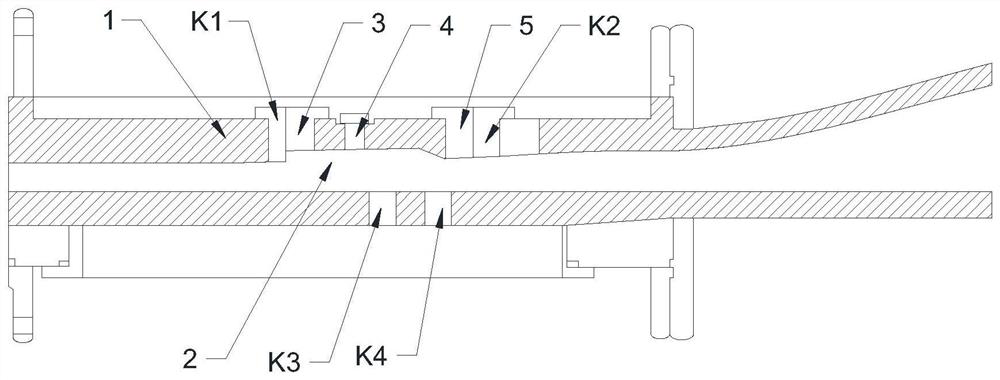
[0026] see figure 1 , a method for promoting scramjet engine to realize start-up ignition, injecting air into the engine vertically to the direction of air flow on one side of the inner wall surface of the scramjet flame stabilizer, and the air flow rate is 15% to 30% of the air flow rate at the engine inlet %, the distance between the injection air position and the engine flame stabilizer position is 10% to 20% of the total length of the engine.

[0027] In this embodiment, the rear part of the scramjet flame stabilizer implements air jet injection, the air is air at a normal temperature of 295K, and the air flow rate is 15% to 30% of the air flow rate at the engine inlet.

[0028] The device used in this embodiment to promote the start and ignition of the scramjet engine includes a flame stabilizer arranged at the front end of the scramjet combustion chamber. The flame stabilizer is provided with a plurality of fuel injection blocks. There are a plurality of nozzle holes co...

Embodiment 2

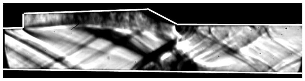
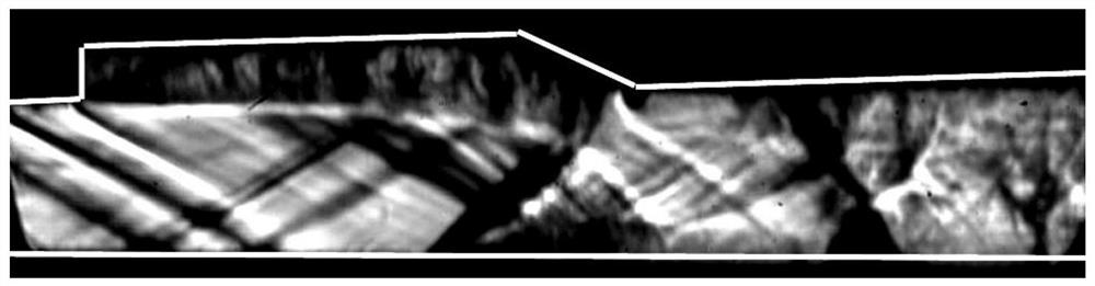
[0032] see Figure 1-7 , the present embodiment will test and compare the similarities and differences of the scramjet flow field structure, start ignition time and flame distribution with and without the action of jet air, to verify the practical application effect brought by the present invention.

[0033] In this embodiment, the configuration of the engine is as figure 1 As shown, the engine model 1 includes a flame stabilizer located at the front end of the combustion chamber, the inlet interface of the isolation section of the combustion chamber is 30mm×150mm, and the total length of the model is 1073.19mm. Engine model 1 uses kerosene as fuel to inject through the fuel injection block. The total air flow rate of the air jet tooling block 5 at normal temperature is about 27.2% of the inlet engine flow rate. Cavity) entrance is about 198.16mm, accounting for about 18.5% of the total length of engine model 1. The upper wall of the flame stabilizer is a cavity 2, and two s...


PUM


Abstract

The invention relates to the technical field of scramjet engines, and discloses a method and device for promoting a scramjet engine to achieve starting ignition. Air is injected into an engine in thedirection perpendicular to the air flowing direction on one side of the inner wall face of a flame stabilizer of the scramjet engine, the air flow is 15%-30% of the air flow of an engine inlet, and the length from the air injection position to the position of the engine flame stabilizer is 10%-20% of the total length of the engine. According to the method and device for promoting the scramjet engine to achieve the starting ignition, air jet injection is implemented at the rear part of the flame stabilizer of the scramjet engine to generate a shock wave string structure, so that thermodynamic parameters of a flow field are influenced, static pressure and static temperature in the flow field are improved, the speed is reduced, efficient mixing of fuel and air is promoted, the injection modeof the fuel or the geometric configuration of the engine does not need to be changed, extra interference does not brought to work of the engine, the scramjet engine can be promoted to achieve the starting ignition, and release of fuel chemical energy of a combustion chamber is ensured.

Description

technical field [0001] The invention relates to the technical field of scramjet engines, in particular to a method and device for promoting scramjet engines to realize starting and ignition. Background technique [0002] In the scramjet flow channel, air flows through the combustion chamber at supersonic speed, and the residence time of fuel in the combustion chamber is extremely short, on the order of milliseconds. In order to realize the normal operation of the scramjet, it is necessary to realize the conversion of fuel chemical energy to thermal energy, that is, to realize the starting and ignition of the scramjet. In particular, the application of kerosene fuel, which is both economical and easy to store, must be premised on the realization of kerosene ignition in the scramjet. [0003] At present, there are many methods to promote the start and ignition of scramjet engines, which are often to change the configuration of the engine combustion chamber or optimize the fue...

Claims


Application Information

Patent Timeline
Patent Type & Authority Applications(China)
IPC IPC(8): F23R3/04F23R3/28
CPCF23R3/04F23R3/286
Inventor 田野钟富宇时文李季肖保国鲁玲李世豪孙光焱张娜
Owner CHINA AERODYNAMICS RES & DEV CENT
Why Eureka
Try Eureka