Hypersonic mechanical transmission frequency modulation pulse injection device and method

A mechanical transmission and hypersonic technology, applied in the direction of mechanical equipment, combined engines, ramjet engines, etc., can solve the problem that the influence of pressure increase is difficult to control, it is not enough to achieve a high degree of fuel mixing, and the mixing process of fuel and incoming flow is long and other problems, to achieve the effect of eliminating the shear layer, avoiding the phenomenon of rich oil flameout, and good crushing and atomization effects

Active Publication Date: 2021-09-07
CHINA AERODYNAMICS RES & DEV CENT
View PDF7 Cites 0 Cited by
  • Summary
  • Abstract
  • Description
  • Claims
  • Application Information

AI Technical Summary

Problems solved by technology

However, there are limitations, mainly including: (1) large-scale turbulent flow can be achieved macroscopically, but it is not enough to achieve a high degree of fuel mixing at the microscopic level; (2) the mixing process of fuel and incoming flow is relatively long, and combustion It is impossible to lengthen the chamber indefinitely, and it is difficult to meet the requirements; (3) The impact of pressure increase caused by enhanced combustion heat release is difficult to control
Therefore, the technology that can actively control the enhanced blending has become a hot research direction, but there are few published articles in the relevant direction at home and abroad. Smith.Leslie A. et al. 2 A simulation experiment was carried out

Method used


Image

  • Hypersonic mechanical transmission frequency modulation pulse injection device and method
  • Hypersonic mechanical transmission frequency modulation pulse injection device and method
  • Hypersonic mechanical transmission frequency modulation pulse injection device and method

Examples


Embodiment 1

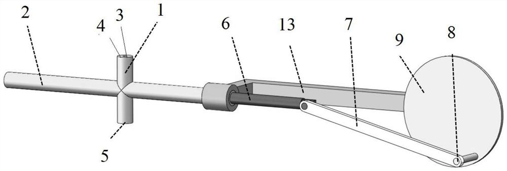
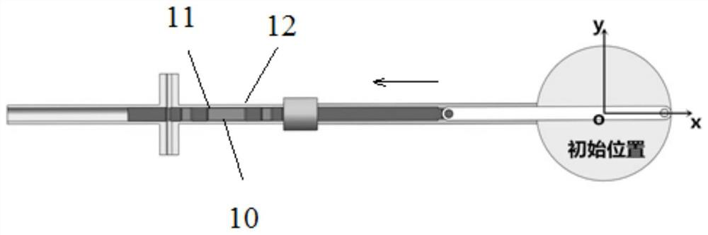
[0040] A hypersonic mechanically driven frequency-modulated pulse injection device, comprising: a longitudinal main body shell 1, a transverse main body shell 2 vertically crossing the longitudinal main body shell 1, an axis 6 is arranged concentrically inside the transverse main body shell 2, and the right end of the axis 6 is connected to a transmission The left end of the rod 7 is hinged, and the right end of the transmission connecting rod 7 is hinged on the high-speed bearing 8 on the driven turntable 9. The driven turntable 9 rotates under the drive of the motor, and the transmission connecting rod 7 drives the axis 6 to reciprocate in a straight line inside the horizontal main body shell 2. movement, a fuel channel 3 is provided inside the longitudinal body shell 2, and the two ends of the fuel channel 3 are fuel inlet 4 and fuel outlet 5 respectively, and a plurality of horizontally arranged injection holes 10 are arranged on the axis, when the axis moves left and right ...

Embodiment 2

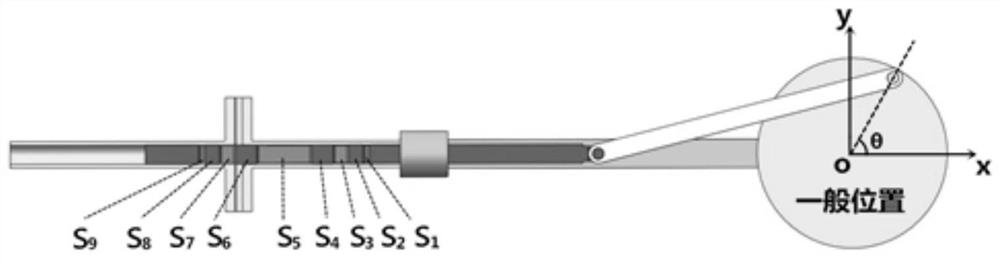
[0050] In this embodiment, the pulse frequency is 400 Hz, the motor speed is 50 revolutions per second, and the spray holes are five square holes, the width of the square holes is equal to the diameter of the fuel inlet, and the spray holes are distributed on the central axis in the x direction within a range of L=90mm, where L=2R, R is the radius of the driven turntable, calculate the length S of the first square hole 1 =3.59mm, length S of the second square hole 3 =8.33mm, the length of the third square hole S 5 =28.96mm, length S of the fourth square hole 7 =8.33mm and the fifth square hole length S 9 =3.59mm; the distance between the square holes satisfies the relational formula: the distance between the first and second holes is S 2 =7.42mm, the distance between the second and third holes is S 4 =11.18mm, the distance between the third and fourth is S 4 =11.18mm, the distance between the fourth and fifth is S 8 =7.42mm.

[0051] The above dimensions are calculated ...

Embodiment 3

[0061] This embodiment provides a method for fuel pulse injection under the condition of hypersonic incoming flow. Using the pulse injection device, the driven turntable rotates under the drive of the motor, and the transmission connecting rod drives the axis to make a straight line inside the lateral main body shell. Reciprocating movement, there is a fuel channel inside the longitudinal main body shell, the two ends of the fuel channel are fuel inlet and fuel outlet respectively, and a plurality of horizontally arranged injection holes are arranged on the axis, when the axis moves left and right to a certain position on it When the front edge of the injection hole and the fuel passage begin to overlap, the fuel passage communicates, and the fuel enters from the fuel inlet and is sprayed out from the fuel outlet. Closed, a pulse process ends until the next injection hole coincides with the fuel channel; the axis moves back and forth continuously to form an on-off period interv...


PUM


Abstract

The invention provides a hypersonic mechanically driven frequency-modulated pulse injection device, an injection method and a design method, including: a longitudinal main body shell, a transverse main body shell, an axis, a transmission connecting rod, a high-speed bearing, a driven turntable, and a driving connecting rod The axis reciprocates in a straight line inside the transverse main body shell, and a fuel channel is provided inside the longitudinal main body shell. When the front edge of an injection hole on which the axis moves left and right and the fuel channel begins to overlap, the fuel channel is connected, and the fuel enters from the fuel inlet and is sprayed out from the fuel outlet until the rear edge of the injection hole is completely separated from the fuel channel. When the coincidence of the fuel channel is closed by the axis, a pulse process ends until the next injection hole coincides with the fuel channel. It can effectively improve the mixing effect of fuel injection under the condition of hypersonic incoming flow.

Description

technical field [0001] The invention belongs to the field of hypersonic technology, in particular to a hypersonic mechanically driven frequency-modulated pulse injection device, an injection method and a design method thereof. Background technique [0002] As the power plant of hypersonic cruise aircraft, hydrocarbon fuel scramjet has the characteristics of low cost and long range when flying below Mach 7. However, inside a scramjet engine with a fast flow rate, the residence time of liquid hydrocarbon fuel is only on the millisecond level, and within this short millisecond time, the process of fuel droplet breaking, atomization and evaporation needs to be completed. The process is related to key issues such as ignition and flame stability. Therefore, in the field of hypersonic wind tunnel tests, ground test equipment such as wind tunnels is used in the fuel injection stage of engine tests. In order to improve the effects of fuel mixing and atomization during the test, it i...

Claims


Application Information

Patent Timeline
Patent Type & Authority Patents(China)
IPC IPC(8): F02K7/14F02K7/20
CPCF02K7/14F02K7/20
Inventor 钟富宇田野时文乐嘉陵李季李世豪孙光焱张娜鲁玲
Owner CHINA AERODYNAMICS RES & DEV CENT
Why Eureka
Try Eureka