Hologram and holographic viewing device incorporating it

Active Publication Date: 2006-04-13
DAI NIPPON PRINTING CO LTD
View PDF4 Cites 12 Cited by
  • Summary
  • Abstract
  • Description
  • Claims
  • Application Information

AI Technical Summary

Benefits of technology

[0013] In view of such problems with the prior art, the primary object of this invention is to provide a hologram that enables two or more varying images to be simul

Problems solved by technology

However, such transmission type holograms as briefed above are shy of variations and interest, because, as long as the relat

Method used


Image

  • Hologram and holographic viewing device incorporating it
  • Hologram and holographic viewing device incorporating it
  • Hologram and holographic viewing device incorporating it

Examples


Embodiment Construction

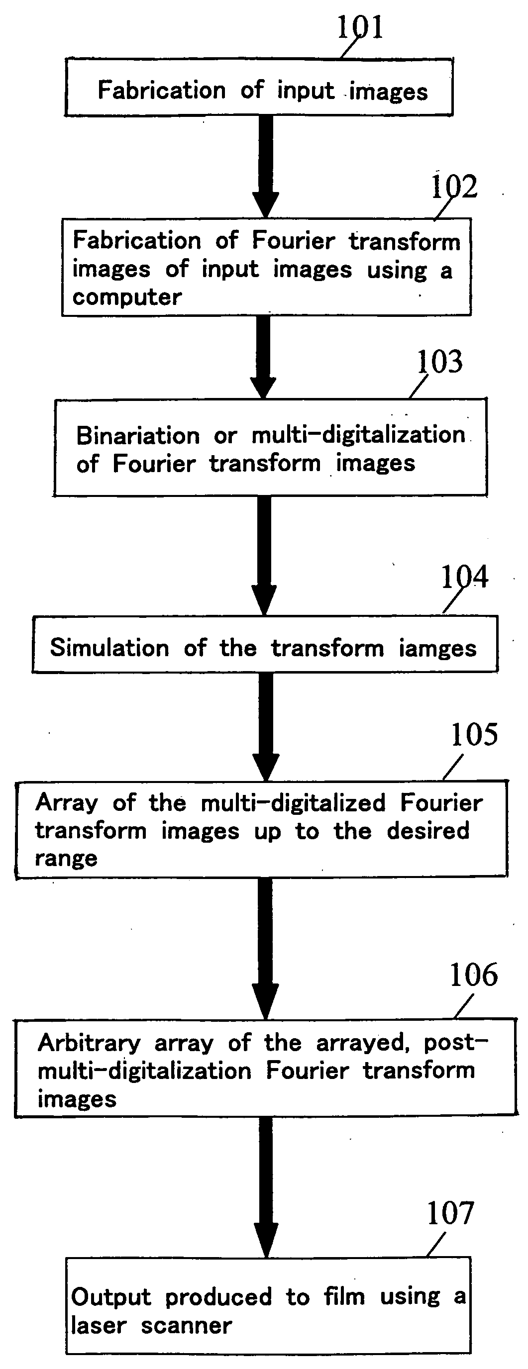
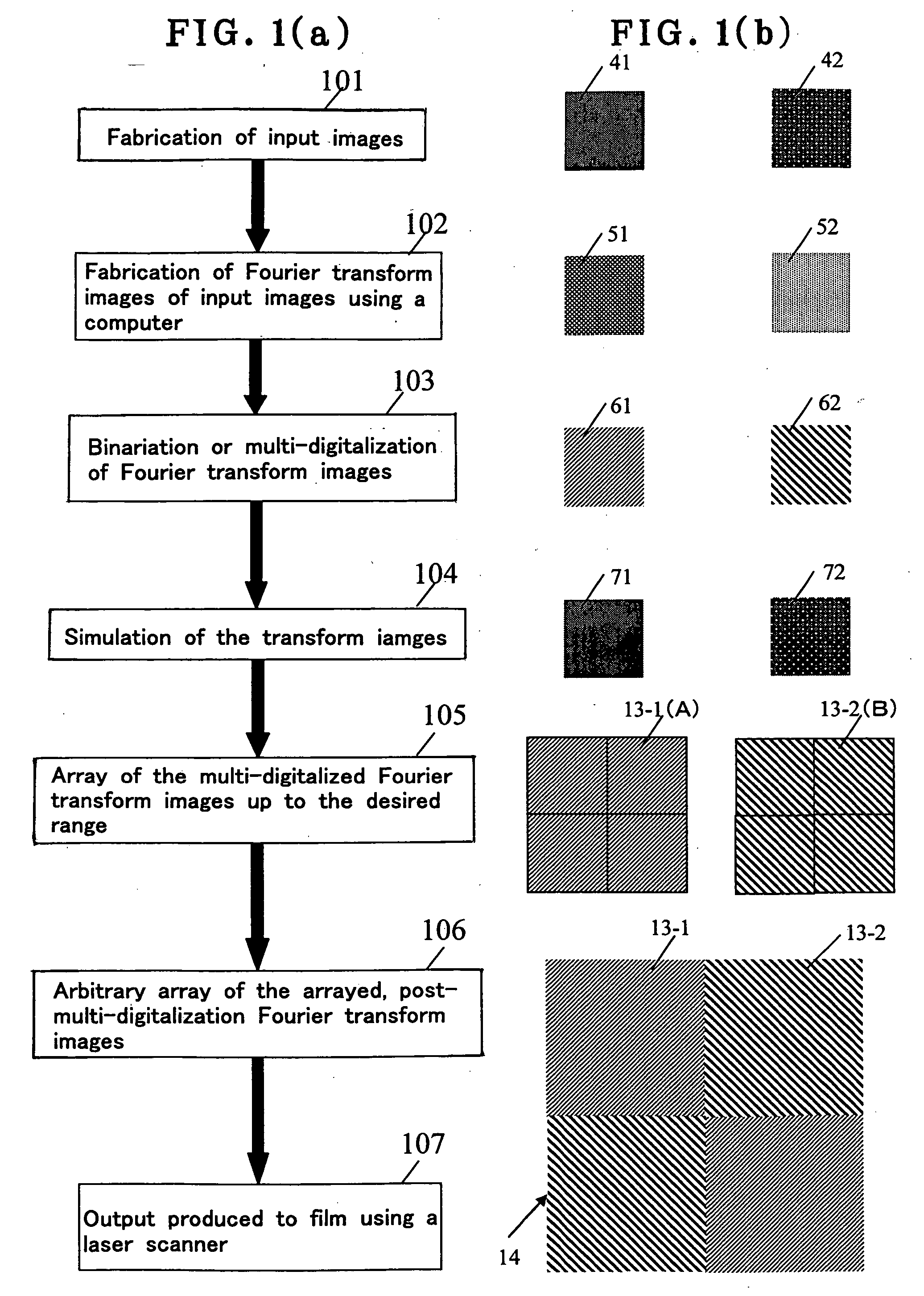
[0039]FIG. 1(a) is a flowchart illustrative of one hologram fabrication process according to the invention, and FIG. 1(b) is illustrative in schematic of that flowchart. First of all, a plurality of input images 41 and 42 are fabricated on a computer (step 101). For instance, the input image 41 has a crescent pattern a, and the input image 42 has a stellar pattern b.

[0040] Then, on the computer, Fourier transform is applied to each input image 41, 42 to fabricate a Fourier transform image 51, 52 (step 102). Each Fourier transform image 51, 52 is binarized or multi-digitalized (step 103). In FIG. 1(b), numeral reference 61 is a Fourier transform image that is multi-digitalized in correspondence to the input image 41 (a diffraction optical element; an element hologram), and 62 is a Fourier transform image (a diffraction optical element; and element hologram) that is multi-digitalized in correspondence to the input image 42.

[0041] Then, the image to be reconstructed is simulated (ste...


PUM


Abstract

The invention relates to a hologram that enables two or more different images to be simultaneously reconstructed even in a state where the hologram is fixed in terms of relative position with respect to an eye, and a holographic viewing device that incorporates it. The hologram 14 is fabricated by applying Fourier transform to a plurality of input image to obtain a plurality of corresponding Fourier transform images 13-1, 13-2 and arraying the Fourier transform images 13-1, 13-2 on the same plane according to a given two-dimensional array principle into a computer-generated hologram. When a plurality of point light sources 231 to 239 located behind the hologram 14 are viewed through the hologram 14, a plurality of images are simultaneously and parallel reconstructed (28) in correspondence to the array positions of the plurality of Fourier transform images.

Description

BACKGROUND OF THE INVENTION [0001] The present invention relates generally to a hologram and a holographic viewing device incorporating it, and more particularly to a holographic viewing device with a built-in computer-generated hologram set up in the form of a transmission type Fourier transform hologram. [0002] Patent Publication 1 comes up with holographic eyeglasses constructed as shown in the perspective view of FIG. 16(a). More specifically, two transmission type holograms 2 and 3 are fitted in a binocular framework of an eyeglass frame 1. As a scene containing light sources 4, 5, 6 and 7, each of small area, as shown in FIG. 16(b), is viewed with the eyeglasses using the transmission type holograms 2 and 3, for instance, it looks as shown in FIG. 16(c). In other words, it looks as if the small-area light sources 4, 5, 6 and 7 in the actual scene of FIG. 16(b) were replaced with pre-selected words “NOEL”8, 9, 10 and 11, respectively. For the transmission holograms 2 and 3 havi...

Claims


Application Information

Patent Timeline
IPC IPC(8): G02B23/00
CPCG03H1/0236G03H1/08G03H1/30G03H2001/306G03H2222/34G03H2001/303
Inventor TANAKA, AKIKO
Owner DAI NIPPON PRINTING CO LTD
Why Eureka
Try Eureka