System and methods for illuminating panels

a technology of lighting panels and lighting elements, applied in the field of lighting panels, can solve the problems of consuming significantly less power, reducing the overall size and weight of the power supply, and significantly longer life of the fluorescent lamp, and achieves the effects of minimal maintenance, high efficiency, and cost-effectiveness

Inactive Publication Date: 2007-10-25
ILLUMINER
View PDF3 Cites 49 Cited by
  • Summary
  • Abstract
  • Description
  • Claims
  • Application Information

AI Technical Summary

Benefits of technology

[0009] To achieve the foregoing and in accordance with the present invention, systems and methods for illuminating panels such as advertising display panels are provided. Such illuminators can be operated very efficiently, cost-effectively and with minimal maintenance once installed in the field.
[0010] In one embodiment of the invention, the illuminated panel includes a panel frame with one or more illuminated frame member. Additional illuminated frame member(s) may be needed depending on the overall dimensions of the illuminated panel. The inside surface of the illuminated frame member should be reflective to increase the light transmission efficiency of the panel.

Problems solved by technology

In addition, florescent lamp-life is significantly longer than incandescent bulbs, and florescent lights also consume significantly less power for the same light output.
While florescent tubes are better than incandescent bulbs for illuminating panels, they also have many disadvantages including overall size and weight of the power supply, and fragility of the glass tube.
For example, because most illuminated panels are less than one-half of an inch thick, the florescent tubes have to be equally skinny and very fragile.
Accordingly, the florescent tubes are easily damaged during manufacture, transportation and installation.
In addition, although florescent tubes have longer lamp-life than incandescent bulbs, florescent tubes have a tendency to flicker depending on the frequency of the driving voltage.
The light output of florescent tubes is also not easily adjusted to match ambient light conditions.
Florescent tubes are also inefficient when operated under low ambient temperatures.
There are also other disadvantages inherent with using single light sources, the most common of which are florescent tubes.
Since florescent tubes are easily damaged when subjected to shock, when the single florescent tube fails, an entire side of the panel is not longer illuminated.
Previous attempts at replacing florescent tubes with point lights sources have failed because point light sources produce a “saw-tooth” effect in the light pattern.

Method used


Image

  • System and methods for illuminating panels
  • System and methods for illuminating panels
  • System and methods for illuminating panels

Examples


Embodiment Construction

[0020] The present invention will now be described in detail with reference to several embodiments thereof as illustrated in the accompanying drawings. In the following description, numerous specific details are set forth in order to provide a thorough understanding of the present invention. It will be apparent, however, to one skilled in the art, that the present invention may be practiced without some or all of these specific details. In other instances, well known process steps and / or structures have not been described in detail in order to not unnecessarily obscure the present invention. The features and advantages of the present invention may be better understood with reference to the drawings and discussions that follow.

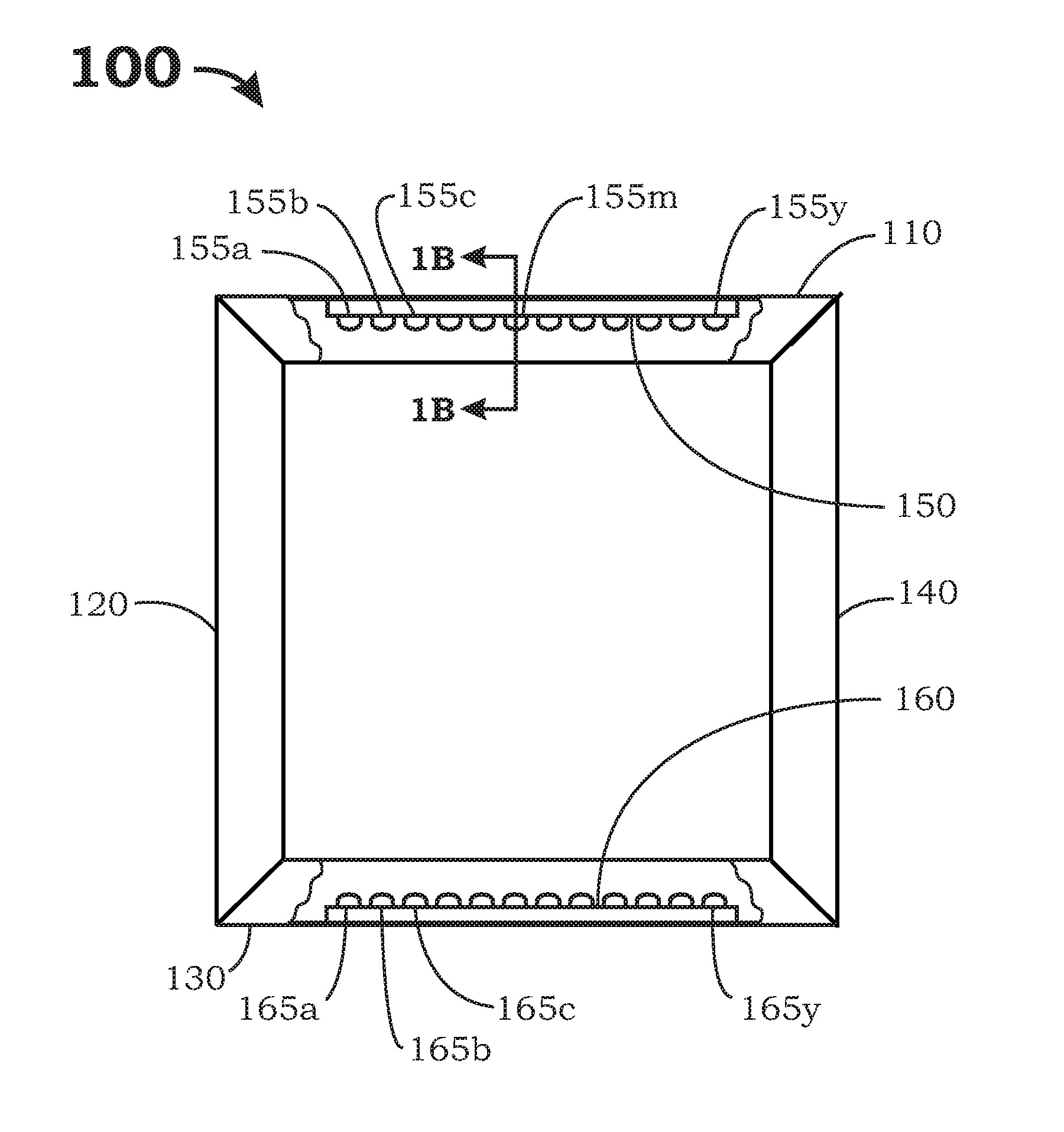
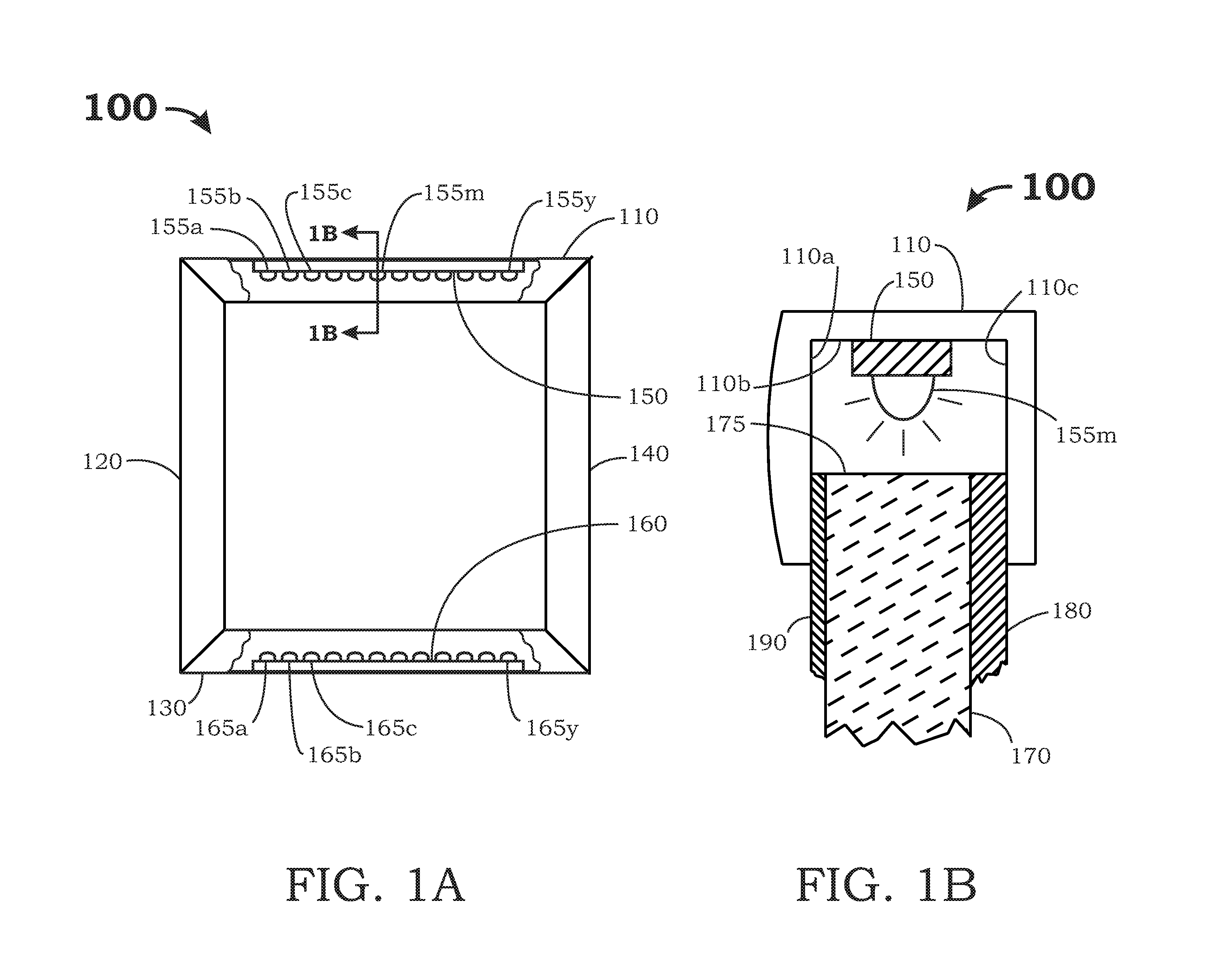
[0021]FIG. 1A is a front view showing one embodiment of an illuminated panel 100 in accordance with the present invention. Panel 100 includes frame members 110, 120, 130, 140. To facilitate discussion, the front portion of top frame member 110 and the front po...


PUM


Abstract

A system for illuminating panels such as advertising display panels is provided. Such illuminated panels can be operated very efficiently, cost-effectively and with minimal maintenance once installed in the field. In one embodiment, the illuminated panel includes a panel frame with one or more illuminated frame member. Additional illuminated frame member(s) may be needed depending on the overall dimensions of the illuminated panel. The inside surface of the illuminated frame member should be reflective to increase the light transmission efficiency of the panel. A row of point light sources, e.g., a row of light emitting diodes, is located within the illuminated frame member. The panel frame encloses a light diffusion layer, e.g., an acrylic sheet, with a diffusion edge facing the row of point light sources. The diffusion edge has a surface roughness configured to diffuse light emitted by the row of point light sources. Suitable surface roughness can be accomplished by saw cuts or sanding the light diffusion layer with a suitable grit. In some embodiments, the illuminated frame member has an internal profile to better focus the light emitted by the light sources towards the diffusion edge. Suitable internal profiles include rounded profiles such as parabolic and elliptical shapes. Further, because the point light sources are discrete components, the panel frame members can take on a variety of shapes including curved shapes.

Description

BACKGROUND OF THE INVENTION [0001] This invention relates generally to illuminating panels. More particularly, this invention relates to cost effective systems and methods for using multiple point light sources such as light emitting diodes (LEDs) to illuminate panels. [0002] Illuminated panels have many uses where evenly lit panels with neutral color temperature are used including advertising display panels, shopping mall directories, restaurant menus, event schedules, and navigational signboards. Other uses for illuminated panels include light-boxes for artists, photographers, architects, design engineers, general contractors and draftsmen. [0003] These illuminated panels can be as small as six inches by six inches, and as large as four feet by eight feet. Depending on their specific applications, weight, cost, panel thickness, and lamp-life, can all be crucial to the successful design, manufacture and marketing of these panels. In addition, environmental requirements such as vibr...

Claims


Application Information

Patent Timeline
Patent Type & Authority Applications(United States)
IPC IPC(8): G09F13/18
CPCG02B6/0036G02B6/0068G02B6/0073G09F13/22G09F13/00G09F13/0413G09F13/14G02B6/0091
Inventor AWAI, GEORGE K.ERNST, MICHAEL DAVID
Owner ILLUMINER
Why Eureka
Try Eureka