
Illumination device for simulation of neon lighting

a technology of illumination device and neon lighting, which is applied in the direction of lighting support device, lighting application, instruments, etc., can solve the problems of difficult fabrication of neon lighting structures, extremely awkward initial handling of neon lighting, installation and/or replacement,

Inactive Publication Date: 2005-10-11
LUMINII PURCHASER LLC
View PDF18 Cites 47 Cited by
  • Summary
  • Abstract
  • Description
  • Claims
  • Application Information

AI Technical Summary

Benefits of technology

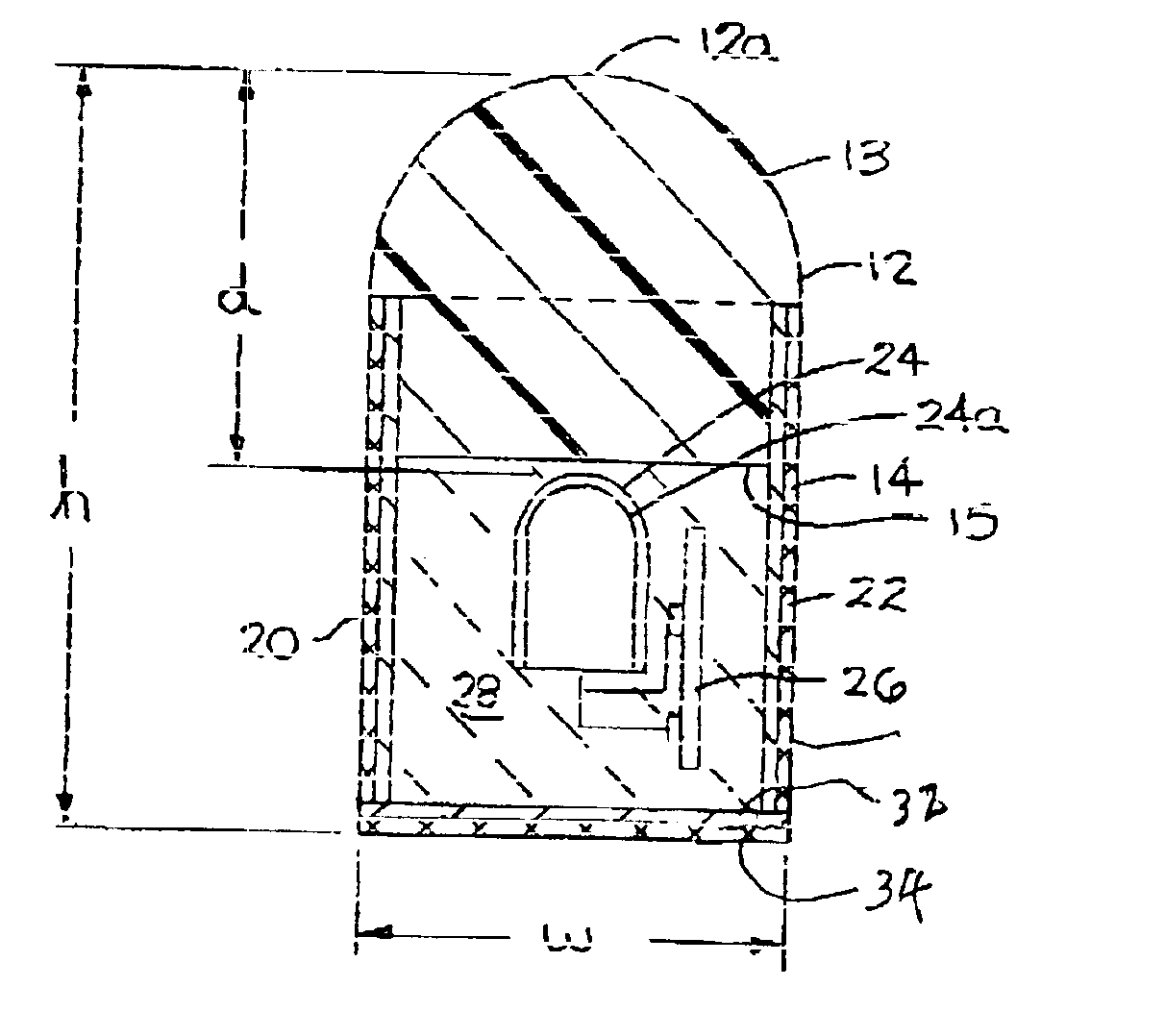
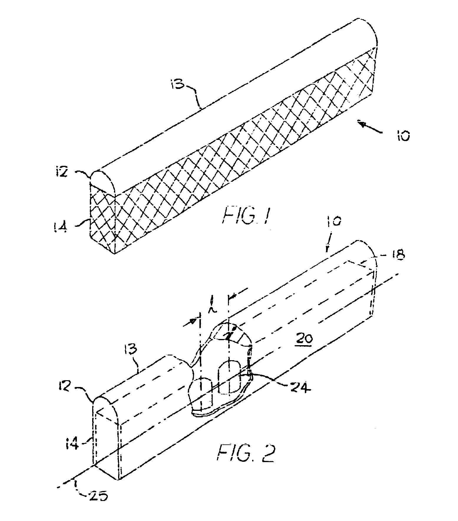
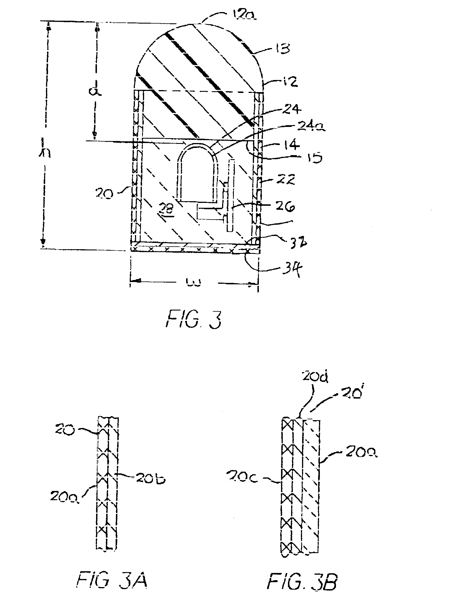
[0012]The present invention utilizes a profiled rod of material having waveguide characteristics that preferentially scatters light entering one lateral surface (“light receiving surface”) so that the resulting light intensity pattern emitted by another lateral surface of the rod (“light emitting surface”) is elongated along the length of the rod. A light source extends along and is positioned adjacent the light receiving surface and spaced from the light emitting surface a distance sufficient to create an elongated light intensity pattern with a major axis along the length of the rod and a minor axis that has a width that covers substantially the entire circumferential width of the light emitting surface. In a preferred arrangement, the light source is a string of point light sources spaced a distance apart sufficient to permit the mapping of the light emitted by each point light source into the rod so as to create elongated and overlapping light intensity patterns along the light emitting surface and circumferentially about the surface so that the collective light intensity pattern is perceived as being uniform over substantially the entire light emitting surface when being viewed from a normal head-on and side perspectives.

Problems solved by technology

Because of the fragility and heavy weight primarily due to its supporting infrastructure, neon lighting is expensive to package and ship.
Moreover, it is extremely awkward to initially handle, install, and / or replace neon lighting structures.
Like this attempt, most prior art neon simulations have resulted in structures difficult to fabricate and providing a little in the way of weight and handling benefits.
However, the twin attributes of neon lighting, uniformity and brightness, have proven to be difficult obstacles to hurdle as such attempts to simulate neon lighting have largely been stymied by the tradeoffs between light distribution to promote the uniformity and brightness.
While the tubing may be lit by such arrangement, the light transfer efficiencies with such an arrangement is likely to result in a “glowing” tube having insufficient intensity to match that of neon lighting.
The use of point light sources such as LEDs may provide intense light that rival or exceed neon lighting, but when arranged in arrays lack the uniformity needed and unfortunately provide alternate high and low intensity regions in the illuminated surfaces.
Attempts to smooth out the light has resulted in lighting that has unacceptably low intensity levels.

Method used


Image

  • Illumination device for simulation of neon lighting
  • Illumination device for simulation of neon lighting
  • Illumination device for simulation of neon lighting

Examples


Embodiment Construction

[0034]To provide the desired result, i.e., an illumination device that is an effective simulator of neon lighting, it is important that the proper materials be selected for the component parts and those parts appropriately and geometrically positioned so that the resulting illumination device has an essentially uniform light intensity distribution pattern over the entire surface with the maximum obtainable brightness. To accomplish this, it is necessary to use a high intensity but dimensionally small light source together with an element that acts both as an optical waveguide and light scattering member, but permits light to exit laterally out of its surface (a “leaky waveguide”). By placing the light source contiguous such a leaky waveguide in a specific manner so as to cause the waveguide to uniformly glow over its lateral surface while maximizing the amount of light exiting the surface, applicants are able to obtain an illumination device that rivals or surpasses the uniform glow...


PUM

PropertyMeasurementUnit
widthaaaaaaaaaa
widthaaaaaaaaaa
widthaaaaaaaaaa

Abstract

An illumination device for simulating neon lighting comprising a plurality of spaced point light sources positioned adjacent a lateral light receiving surface of a substantially rod-like waveguide made of a material that preferentially scatters light entering the light receiving surface such that the light intensity pattern exiting a lateral light emitting surface of the waveguide has a substantially uniform light intensity pattern.

Description

[0001]This application claims priority from Provisional Application No. 60 / 265,522 filed Jan. 31, 2001 entitled Simulated Neon Lighting for Illumination of Objects, and is a continuation of U.S. application Ser. No. 09 / 982,705 filed on Oct. 18, 2001, now U.S. Pat. No. 6,592,238.BACKGROUND OF THE INVENTION[0002]The present invention relates to illumination devices using optical waveguide and, more particularly, to lighting devices for the simulation of neon lighting using optical waveguides and high intensity low voltage light sources and ideally adapted for signage and advertising uses.[0003]Neon lighting, produced by the electrical stimulation of the electrons in the low pressure neon gas filled glass tube, has been a main stay in advertising and for outlining channel letters and building structures for many years. A characteristic of neon lighting is that the tubing encompassing the gas has an even glow over its entire length irrespective of the viewing angle. This characteristic ...

Claims


Application Information

Patent Timeline
Patent Type & Authority Patents(United States)
IPC IPC(8): F21S4/00F21V23/04F21K99/00G02B6/00F21S2/00F21S8/00F21S8/04F21V5/00F21V7/10F21V8/00F21V15/01F21V31/04F21W111/00F21Y101/02G09F13/20G09F13/22G11B11/00
CPCF21S4/007F21V5/00G02B6/0001G02B6/0021G02B6/0073G09F13/22Y10S362/80F21V15/013F21V23/0407F21V31/04F21Y2101/02G02B6/0065G02B6/0068F21Y2103/003F21S8/036F21S4/26F21Y2103/10F21Y2115/10F21S4/00
Inventor CLEAVER, MARK JOSEPHERIKSSON, ERIC OLAVHULSE, GEORGE R.
Owner LUMINII PURCHASER LLC
Learn More