Method and Arrangement for a Rapid and Robust Chromatic Confocal 3D Measurement Technique

a chromatic confocal and 3d measurement technology, applied in the direction of image data processing, measurement devices, instruments, etc., can solve the problems of difficult evaluation, limited depth measurement and depth resolution, and insufficient economic use of the area sensor

Active Publication Date: 2009-01-22
SIRONA DENTAL SYSTEMS
View PDF4 Cites 49 Cited by
  • Summary
  • Abstract
  • Description
  • Claims
  • Application Information

AI Technical Summary

Benefits of technology

[0010]The objective of the present invention is to provide a universally applicable optical measuring method and measuring system with calibration for fast, three-dimensional measurement in commercial applications.

Problems solved by technology

Thus, the achievable depth measurement and depth resolution are limited.
Because of the shift of adjacent spectra, this technique has the reputation of being complicated for evaluation and the area of the area sensor is not used economically as there is no high area filling factor.

Method used


Image

  • Method and Arrangement for a Rapid and Robust Chromatic Confocal 3D Measurement Technique
  • Method and Arrangement for a Rapid and Robust Chromatic Confocal 3D Measurement Technique
  • Method and Arrangement for a Rapid and Robust Chromatic Confocal 3D Measurement Technique

Examples


Embodiment Construction

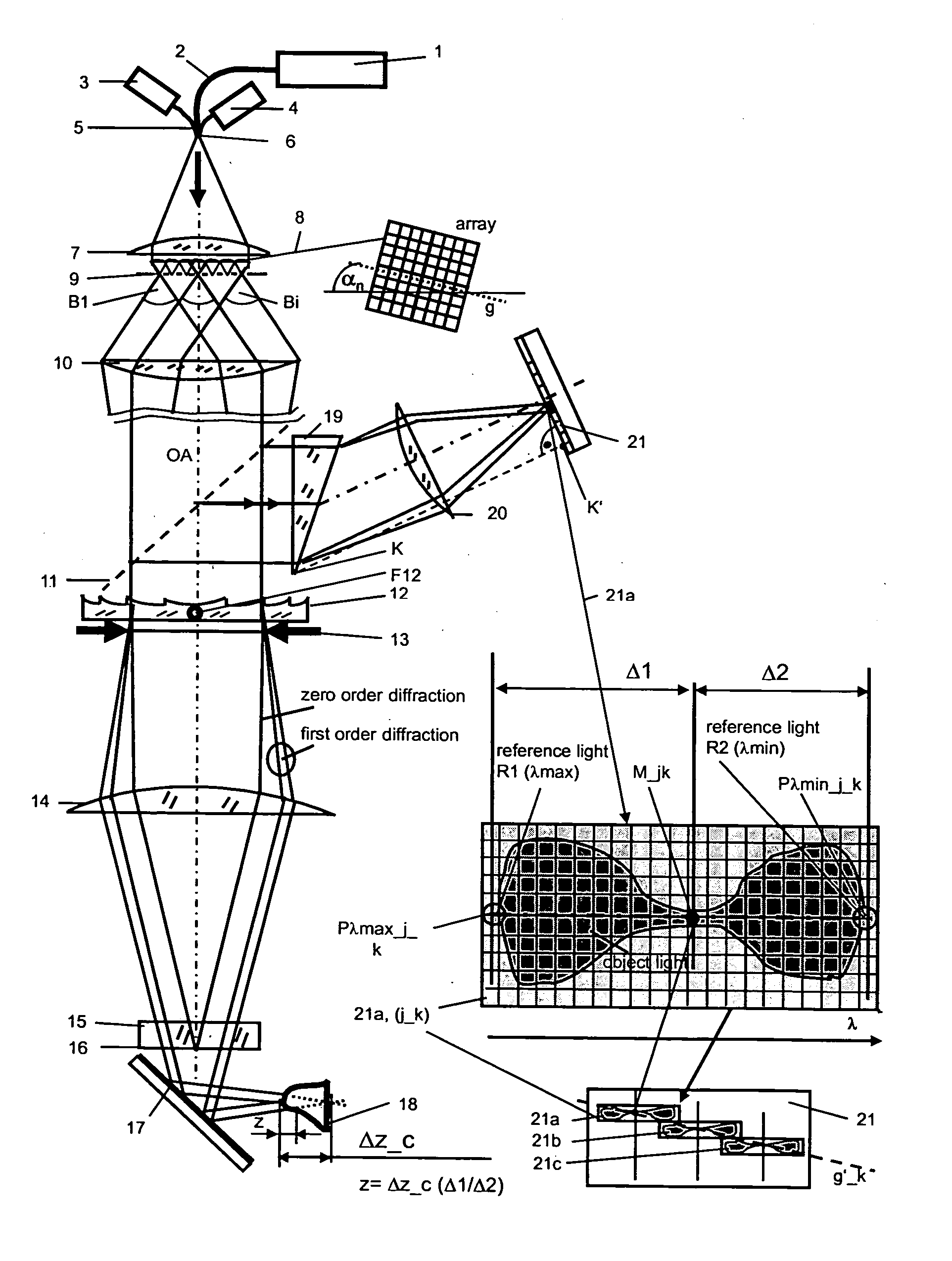
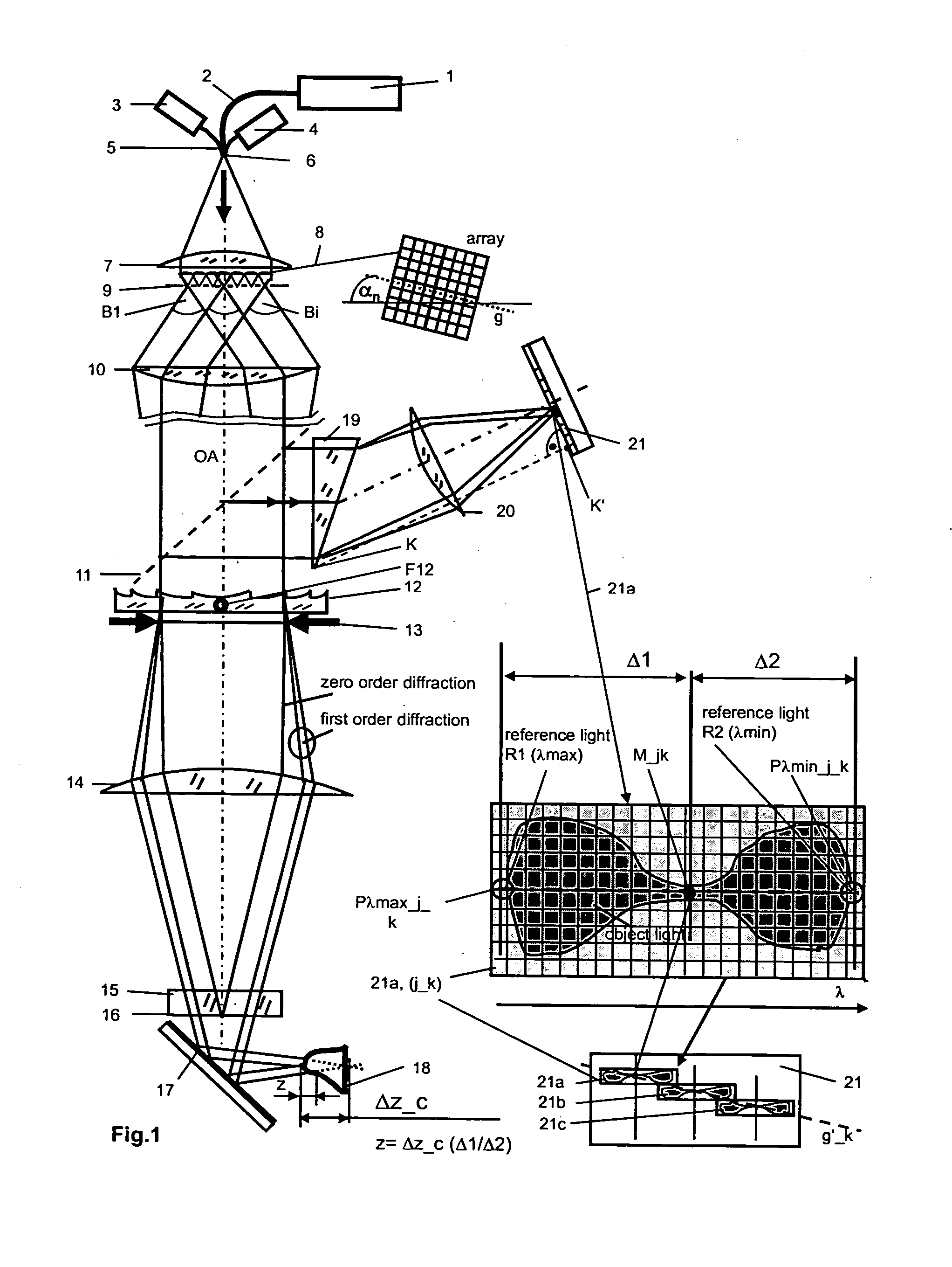
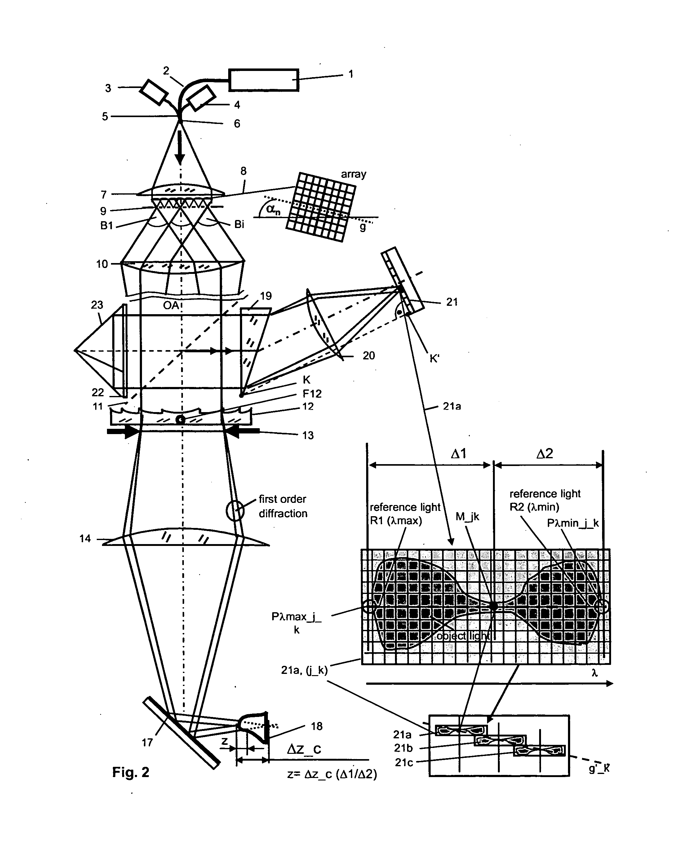
[0014]Method and system for achieving a chromatic confocal technique for three-dimensional measurement of the shape of an object or the shape and position of one or more objects, including measurement on a microscopic scale, particularly also for a tooth or teeth in the jaw of a human being, in which the following components are used: a planar array of polychromatic point light sources, with at least one upstream polychromatic light source as well as at least one passive rastered component, the polychromatic point light sources being adapted to generate a multiplicity of light bundles, a beam splitter, at least one element having a refractive power that is wavelength-dependent for chromatic depth resolution, at least one planar, preferably pixeled, detector matrix in the path of the detection beam, upstream of which detector matrix means for lateral spectral splitting and means for focusing onto the detector matrix are disposed, and a measuring lens for illuminating and imaging the ...


PUM


Abstract

The invention relates to a chromatic confocal technique method and arrangement for the rapid three-dimensional measurement, in particular, of object shape, more particularly of a tooth in the jaw of a human being with an array of polychromatic point light sources, a planar detector matrix, arranged before means for lateral spectral separation and an objective for object illuminating and recording. According to the invention, spectral defined reference light bundles are generated also using components of the arrays of point light sources for chromatic calibration, wherein said reference light bundles are injected into the detection beam path via a reference bean path for chromatic lateral separation and then focused on the detector matrix as reference image points. Spectral reference points are calculated at the detector matrix positions and sub-matrices for spectral analysis of object light are digitally stored with pixel accuracy by means of the above positions which then serve for obtaining measurement points such that the detector matrix may be completely filled out with oblong sub-matrices, the planar array is arranged on the planar detector matrix rotated about an acute angle to the spectral axis, wherein the rotation is carried out about the optical axis (OA) of the arrangement, such that a connecting line of point light sources on projection thereof in the plane of the detector matrix includes an acute angle there with the spectral axis, the λ-axis.

Description

PRIOR ART[0001]Confocal microscopy was proposed by Marvin Minski (cf. U.S. Pat. No. 3,013,467, Dec. 19, 1961).[0002]The chromatic confocal technique provides the possibility of effecting focusing without mechanically moving parts, which as a result usually reduces measuring time significantly, as was proposed by G. Molesini in 1983 in connection with a spectrometer (cf. GB 2144537 and DE 3428593 C2). An example of successful application of the chromatic confocal approach is described in a paper by H. J. Tiziani and H.-M. Uhde “Three-dimensional image sensing by chromatic confocal microscopy” in Applied Optics, Vol. 33, No. 1, April 1994, pages 1838 to 1843. In this case the spectral analysis is performed using three color filters. Thus, the achievable depth measurement and depth resolution are limited.[0003]Patent DE 103 21 885 A1 describes a chromatic confocal system including a component having variable refractive power, for example, a diffractive component. In the arrangement sho...

Claims


Application Information

Patent Timeline
Patent Type & Authority Applications(United States)
IPC IPC(8): G01B11/24
CPCG01B11/25G06T7/0057G01B2210/50G06T7/521
Inventor KORNER, KLAUSKOHLER, CHRISTIANPAPASTATHOPOULUS, EVANGELOSOSTEN, WOLFGANG
Owner SIRONA DENTAL SYSTEMS
Why Eureka
Try Eureka