


Quick Research
Generate reliable direction feasibility study reports for your R&D in just a few steps.

Technical Q&A
Discover and master advanced knowledge NOW. Basics, ideas, possibilities, all at once.

Find Solutions
As an expert in R&D theories, this can generate solutions to your technical problems instantly.

Evaluate Feasibility
Analyze your overall solution with one click, know your potential R&D risks in advance.

Monitor Landscape
Get weekly tech updates, stay abreast of the latest tech innovations and key insights.
Zoom lens system
a zoom lens and zoom technology, applied in the field of zoom lens systems, can solve the problems of affecting the overall length of the overall length of the overall length of the overall length of the overall length, unable to achieve the required optical performance, and the inability of higher-definition imaging devices in recent years to achieve sufficient optical performance with the zoom lens system, etc., to achieve the effect of correcting aberrations
- Summary
- Abstract
- Description
- Claims
- Application Information
AI Technical Summary
Benefits of technology
Problems solved by technology
Method used
Image

Examples
embodiment 1
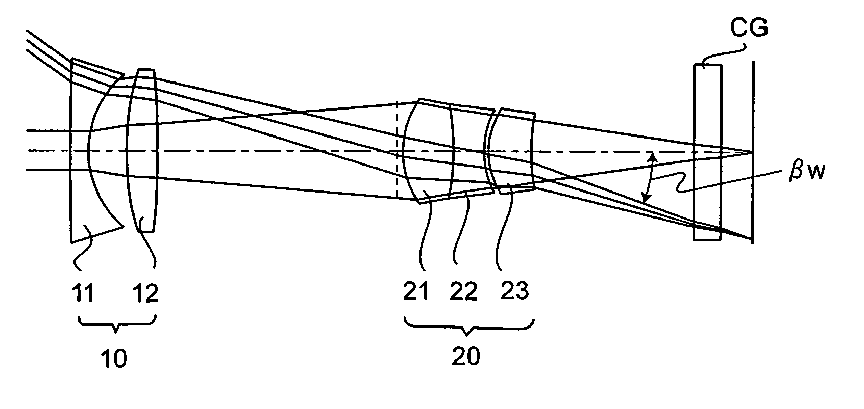
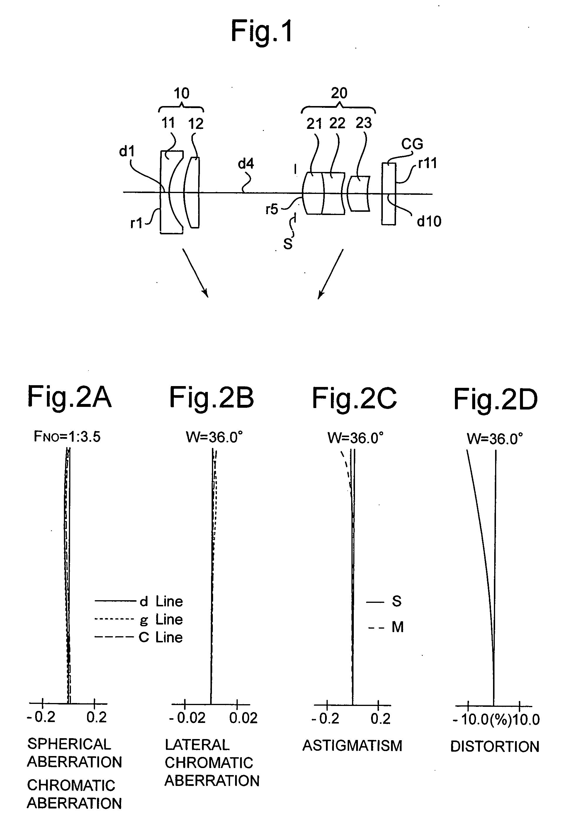
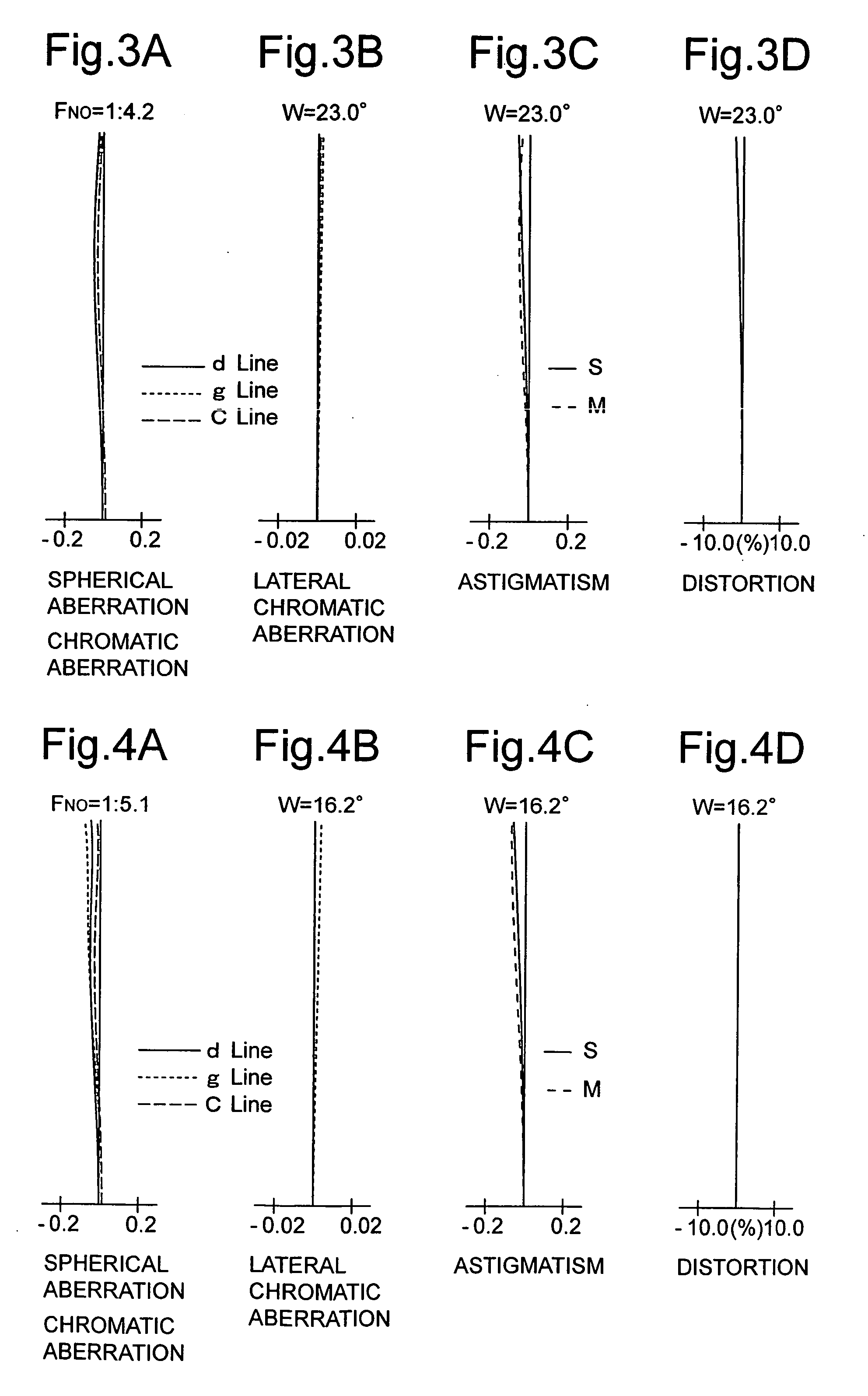
[0137]FIG. 1 is the lens arrangement of the zoom lens system according to the first embodiment of the present invention. FIGS. 2A through 2D show aberrations occurred in the lens arrangement shown in FIG. 1, at the short focal length extremity. FIGS. 3A through 3D show aberrations occurred in the lens arrangement shown in FIG. 1, at an intermediate focal length. FIGS. 4A through 4D show aberrations occurred in the lens arrangement shown in FIG. 1, at the long focal length extremity. Table 1 shows the numerical data of the first embodiment.
[0138] The negative first lens group 10 includes a negative lens element 11 and a positive lens element 12, in this order from the object.
[0139] The positive second lens group 20 includes a positive lens element 21, a negative lens element 22, and a positive lens element 23, in this order from the object. The positive lens element 21 and the negative lens element 22 are cemented.
[0140] The diaphragm S is positioned 0.50 in front of the positive ...
embodiment 2
[0142]FIG. 5 is the lens arrangement of the zoom lens system according to the second embodiment of the present invention. FIGS. 6A through 6D show aberrations occurred in the lens arrangement shown in FIG. 5, at the short focal length extremity. FIGS. 7A through 7D show aberrations occurred in the lens arrangement shown in FIG. 5, at an intermediate focal length. FIGS. 8A through 8D show aberrations occurred in the lens arrangement shown in FIG. 5, at the long focal length extremity. Table 2 shows the numerical data of the second embodiment.
[0143] The basic lens arrangement of the second embodiment is the same as that of the first embodiment.
[0144] The diaphragm S is positioned 0.20 in front of the positive second lens group 20 (in front of surface No. 5).
TABLE 2FNO. = 1:3.5-4.3-6.0f = 4.50-7.00-12.60 (Zoom Ratio 2.80)W = 35.4-22.9-13.0fB = 1.07-1.07-1.07Maximum Image Height = 2.9βW = 20.9βT = 15.4Surf. No.rdNdν1125.0000.601.8348142.723.3731.10—— 3*8.7821.001.7847225.7 4*−417.16...
embodiment 3
[0146]FIG. 9 is the lens arrangement of the zoom lens system according to the third embodiment of the present invention. FIGS. 10A through 10D show aberrations occurred in the lens arrangement shown in FIG. 9, at the short focal length extremity. FIGS. 11A through 11D show aberrations occurred in the lens arrangement shown in FIG. 9, at an intermediate focal length. FIGS. 12A through 12D show aberrations occurred in the lens arrangement shown in FIG. 9, at the long focal length extremity. Table 3 shows the numerical data of the third embodiment.
[0147] The basic lens arrangement of the third embodiment is the same as that of the first embodiment.
[0148] The diaphragm S is positioned 0.20 in front of the positive second lens group 20 (in front of surface No. 5).
TABLE 3FNO. = 1:3.4-4.2-6.1f = 4.40-7.00-13.20 (zoom Ratio 3.00)W = 35.9-23.0-12.4fB = 1.06-1.06-1.06Maximum Image Height = 2.9βW = 19.8βT = 15.4Surf. No.rdNdν1125.0000.601.8340040.923.3521.26—— 3*12.1511.001.8466623.8 4*−53...
PUM
 Abstract
Description
Claims
Application Information
 - R&D Engineer
- R&D Manager
- IP Professional
- Industry Leading Data Capabilities
- Powerful AI technology
- Patent DNA Extraction
Browse by: Latest US Patents, China's latest patents, Technical Efficacy Thesaurus, Application Domain, Technology Topic, Popular Technical Reports.
© 2024 PatSnap. All rights reserved.Legal|Privacy policy|Modern Slavery Act Transparency Statement|Sitemap|About US| Contact US: help@patsnap.com