Oil burner nozzle

Inactive Publication Date: 2006-04-20
CERTAINTEED CORP
View PDF1 Cites 13 Cited by
  • Summary
  • Abstract
  • Description
  • Claims
  • Application Information

AI Technical Summary

Benefits of technology

[0007] In some embodiments, a burner assembly for a furnace includes: a burner block having a front face and a flame cavity with a flame cavity

Problems solved by technology

The location of this tip 32 and the resultant location of the flame emanating from the tip often allows for an undesirable amount of heat exchange in the ext

Method used


Image

  • Oil burner nozzle
  • Oil burner nozzle

Examples


Embodiment Construction

[0011] U.S. Provisional Patent Application No. 60 / 620,460, filed Oct. 19, 2004, is incorporated by reference herein as though set forth in its entirety below.

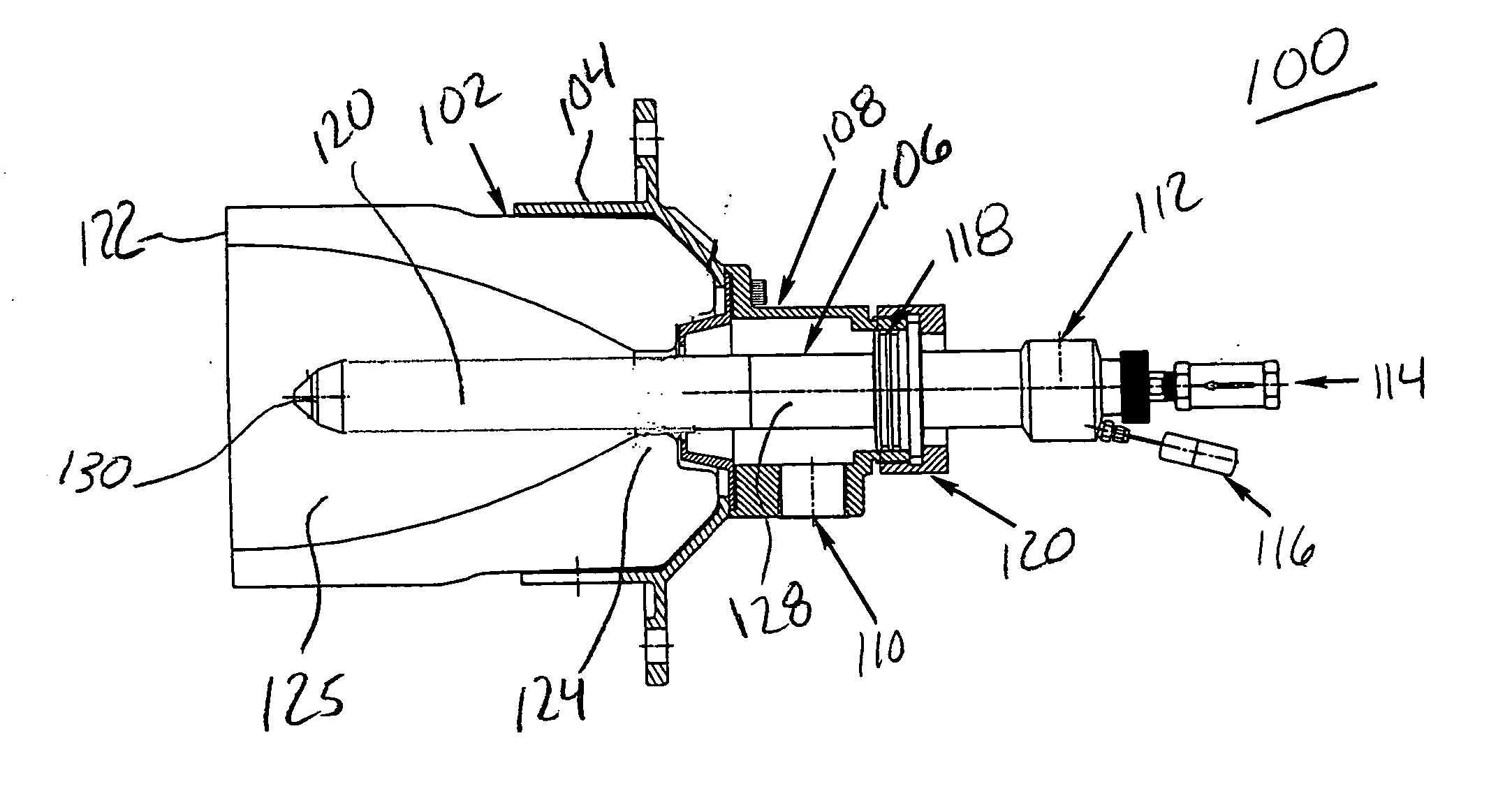
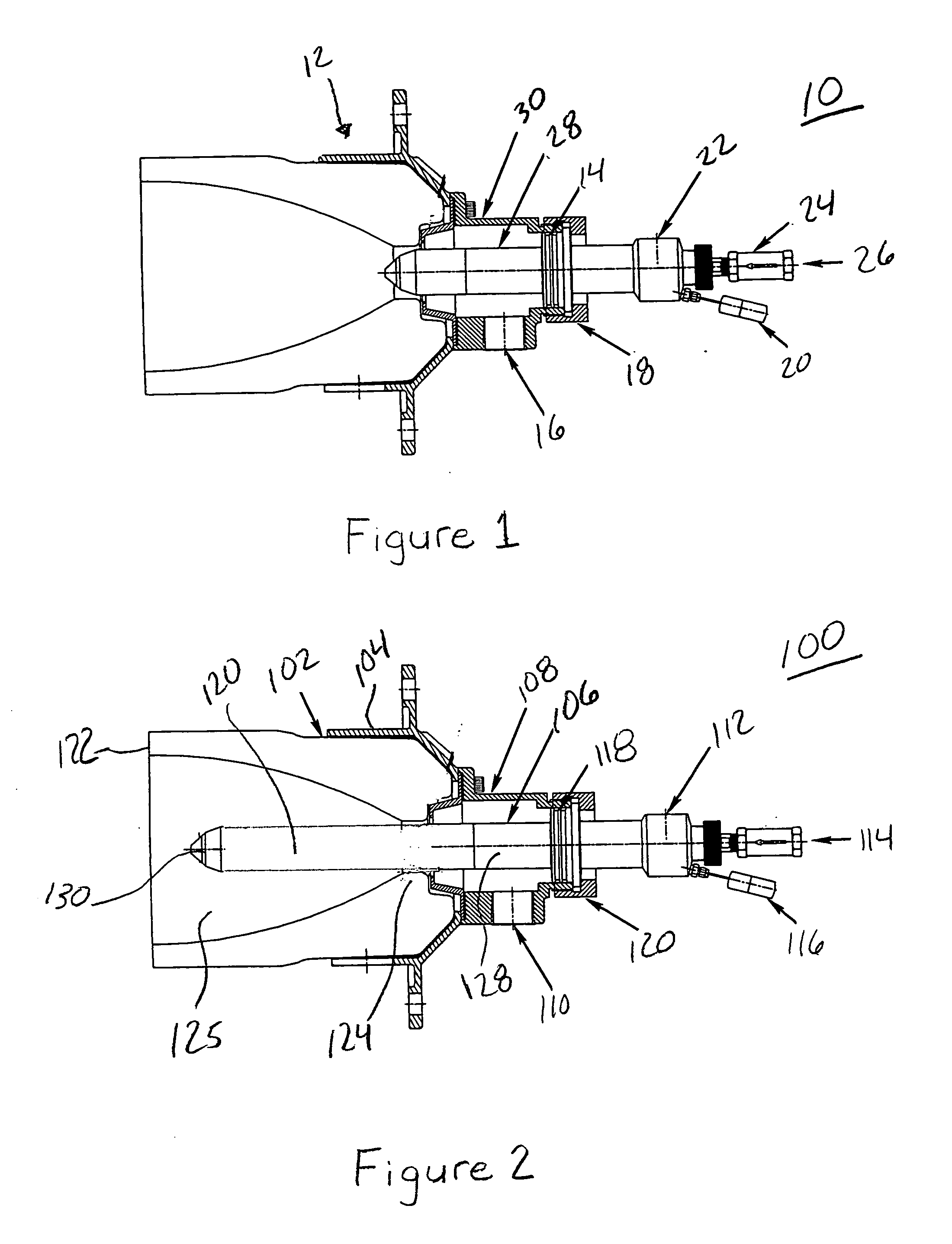
[0012] This description of the exemplary embodiments is intended to be read in connection with the accompanying drawings, which are to be considered part of the entire written description. In the description, relative terms such as “lower,”“upper,”“horizontal,”“vertical,”, “above,”“below,”“up,”“down,”“top” and “bottom” as well as derivative thereof (e.g., “horizontally,”“downwardly,”“upwardly,” etc.) should be construed to refer to the orientation as then described or as shown in the drawing under discussion. These relative terms are for convenience of description and do not require that the apparatus be constructed or operated in a particular orientation. Terms concerning attachments, coupling and the like, such as “connected” and “interconnected,” refer to a relationship wherein structures are secured or attached to one anot...


PUM


Abstract

A burner assembly for a furnace includes: a burner block having a flame cavity with a flame cavity length, and an oil nozzle insert having a tip that extends into the flame cavity by a distance of greater than one tenth of the flame cavity length.

Description

[0001] This application claims the benefit of U.S. Provisional Patent Application No. 60 / 620,460, filed Oct. 19, 2004.FIELD OF THE INVENTION [0002] The present invention relates to glass melting furnaces, and more particularly to improved burners for glass melting furnaces. BACKGROUND OF THE INVENTION [0003] Furnaces used in heating thermal loads, such as glass and metal melts, typically incorporate one or more burners set within burner blocks along the sides of the furnace. The burner produces the required heat by burning a liquid fuel, such as fuel oil or a gaseous fuel such as natural gas in an oxidant such as oxygen or oxygen-enriched air. The resultant flame extends over the melt, and heat is transferred from the flame to the melt by radiation and conduction. [0004]FIG. 1 shows a prior art burner 10 of the type employed in glass melting furnaces. Burner 10 includes a block and frame assembly 12, a combustion oxygen inlet 16, an insert nut 18, a thermocouple 20, an atomizing oxy...

Claims


Application Information

Patent Timeline
IPC IPC(8): F23D11/00
CPCF23C5/06F23M5/025
Inventor BERG, TERRY L.STAHL, MARKUS H.
Owner CERTAINTEED CORP
Why Eureka
Try Eureka