Flexible bathtub waste pipe assembly for bathtubs and the like

a waste pipe and bathtub technology, applied in the field of bathtub waste pipe assembly, can solve the problems of increasing the cost of the assembly, increasing the complexity of installation, and difficult installation of rigid pipes, and achieve the effect of convenient installation

Inactive Publication Date: 2006-04-27
WCM IND INC
View PDF4 Cites 31 Cited by
  • Summary
  • Abstract
  • Description
  • Claims
  • Application Information

AI Technical Summary

Benefits of technology

[0004] A still further object of the invention is to provide a bathtub wast

Problems solved by technology

These rigid pipes are often difficult to install in the tight spaces about a bathtub.
Additionally, these rigid assemb

Method used


Image

  • Flexible bathtub waste pipe assembly for bathtubs and the like
  • Flexible bathtub waste pipe assembly for bathtubs and the like
  • Flexible bathtub waste pipe assembly for bathtubs and the like

Examples


Embodiment Construction

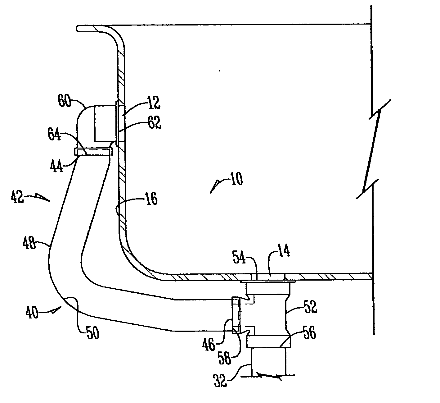
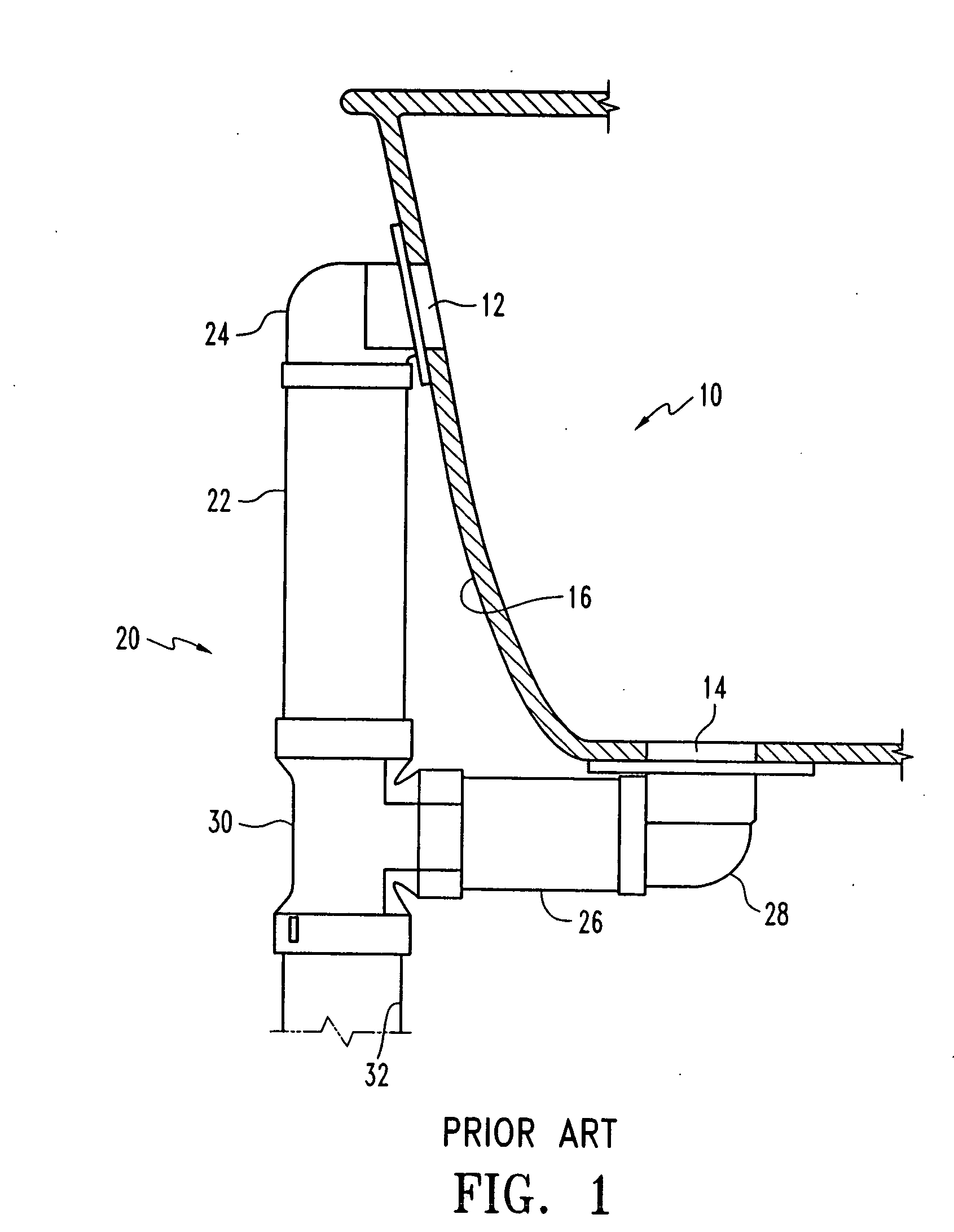
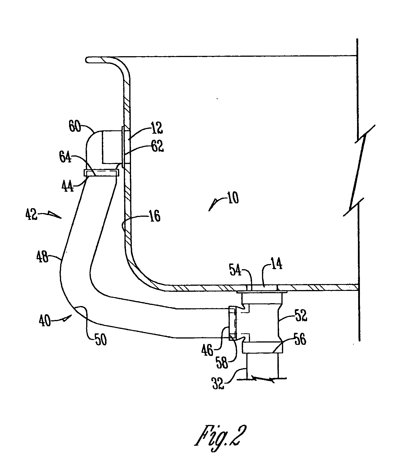
[0012] With reference to FIG. 1, a conventional bathtub 10 has an upper overflow drain 12 and a lower drain 14. The upper overflow drain 12 is located at one end 16 of the bathtub 10 for draining overflow fluids from the bathtub 10. The lower drain 14 is located in the bottom of the bathtub 10 for draining fluids from the bottom of the bathtub 10.

[0013] A conventional prior art rigid waste pipe assembly 20 has an upper rigid pipe 22 oriented in a vertical direction. The pipe 22 is connected to the bathtub upper overflow drain 12 via an upper rigid connector 24. The pipe assembly 20 also has a lower rigid pipe 26 oriented in a horizontal direction. The pipe 26 is connected to the lower drain 14 via a lower rigid connector 28. The pipe 22 and the pipe 26 are joined at a rigid three-way connector 30. The connector 30 receives fluid from both the upper overflow drain 12 and lower drain 14, and directs the fluid to a bottom outlet 32.

[0014] Referring now to FIG. 2, a bathtub waste pipe...


PUM


Abstract

A bathtub waste pipe assembly for draining fluid from a bathtub where the bathtub has an upper overflow drain and a lower drain. The bathtub waste pipe assembly includes a flexible hollow tube extending from the upper overflow drain to the lower drain.

Description

BACKGROUND OF THE INVENTION [0001] In plumbing of bathtubs, existing rigid waste pipe assemblies are used to receive the effluent fluid from the bathtub. These rigid pipes are often difficult to install in the tight spaces about a bathtub. Further, these rigid pipes need to either be properly sized in length, or cut down to a proper length to be installed with the bathtub. Additionally, these rigid assemblies include a multiplicity of pieces, adding to the cost of the assembly, as well as the complexity of installation. [0002] It is therefore an object of this invention to provide a bathtub waste pipe assembly including a flexible hollow tube, wherein the installation of the bathtub waste pipe assembly is simplified. [0003] A further object of the invention is to provide a bathtub waste pipe assembly wherein the length of assembly need not be specifically sized prior to installation. [0004] A still further object of the invention is to provide a bathtub waste pipe assembly wherein t...

Claims


Application Information

Patent Timeline
IPC IPC(8): E03C1/22E03C1/24
CPCE03C1/232
Inventor BALL, WILLIAM T.
Owner WCM IND INC
Why Eureka
Try Eureka