Brushless motor and method of manufacturing the same

a brushless motor and motor body technology, applied in the field of brushless motors, can solve the problems of increasing the leakage of lubricating oil from the oilless bearing, difficult to design dynamic pressure fluid bearings, and unsuitable for changing rotation speed, etc., to achieve the effect of reducing the loss of bearings and ensuring the rigidity of bearings

Inactive Publication Date: 2006-04-27
MINEBEA MOTOR MFG
View PDF3 Cites 21 Cited by
  • Summary
  • Abstract
  • Description
  • Claims
  • Application Information

AI Technical Summary

Benefits of technology

[0014] With this configuration, the motor acts as an oilless bearing at low rpm and as a hydrodynamic bearing at high rpm. Thus, it is possible to suppress an increase in bearing loss while obtaining necessary bearing stiffness at high rpm. This configuration is suitable for a motor for driving an optical disk changing in rotation speed over a wide range during repeated start-and-stop operations.

Problems solved by technology

When bubbles occurs in the bearing or bubbles expand due to a temperature rise or a pressure reduction, bubbles compressed by a dynamic pressure easily enter the sintered holes and increase the leakage of lubricating oil from the oilless bearing.
Such motors are suitable for high-speed and constant-speed operations but are not suitable for uses in changing a rotation speed over a wide range due to frequent start and stop of high-speed and constant-speed operations.
Thus, it is quite difficult to design dynamic pressure fluid bearings.
Particularly in the hybrid bearing of Japanese Patent Laid-Open No. 10-196646, working is necessary to make the part of bearing for generating a dynamic pressure larger in capillary force than the sintered hole of the oil impregnated sintered bearing, thereby increasing restrictions.
However, the brushless motor which requires changing a rotation speed over a wide range faces another problem.
In addition, the sleeve may be worn and cause seizing.
Particularly in the case of Japanese Patent Laid-Open No. 2001-124057, since the herringbone groove is formed on the output end of the shaft, it is necessary to fill sintered holes on the inner surface of the sleeve facing the herringbone groove to prevent lubricating oil from being pressed back into the sleeve, so that the function of the oilless bearing is lost.
Hence, after start-and-stop operations are repeated, the sleeve facing the herringbone groove is like to wear and cannot stand many hours of operation.

Method used


Image

  • Brushless motor and method of manufacturing the same
  • Brushless motor and method of manufacturing the same
  • Brushless motor and method of manufacturing the same

Examples


Embodiment Construction

[0021] Referring to an embodiment shown in FIGS. 1 to 5, a brushless motor of the present invention will be described below.

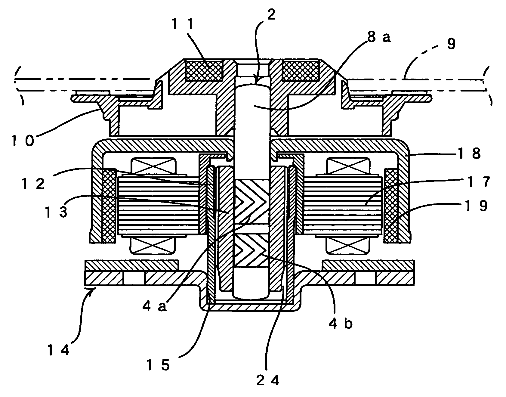
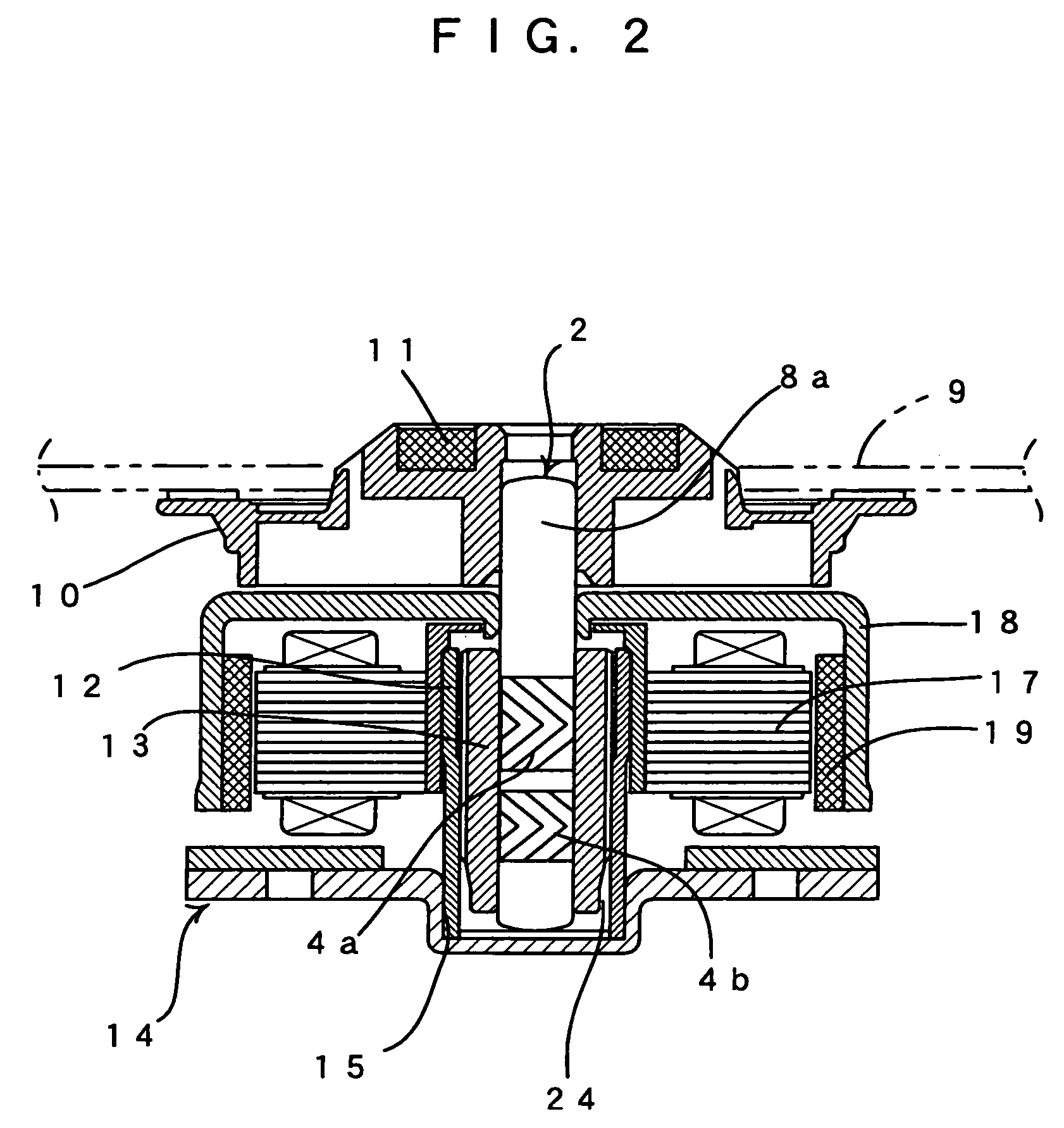
[0022]FIG. 2 shows the brushless motor of the present invention. A turntable 10 for holding a disk recording medium 9 is attached to a loading end 8a of a shaft 2. A clamper is not illustrated which is attracted to a magnet 11 on the turntable 10 such that the disk recording medium 9 is integrally interposed between the clamper and the turntable 10.

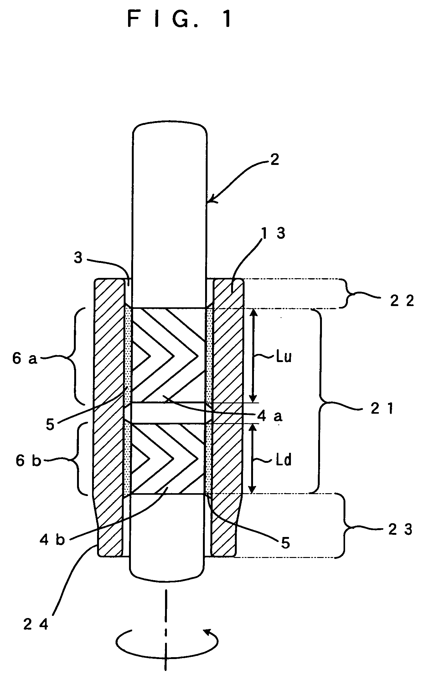
[0023] The brushless motor is assembled in the steps of FIGS. 3A and 3B and FIGS. 4A to 4F. The brushless motor uses an internal bearing formed by combining the shaft 2, on which herringbone grooves 4a and 4b are formed as dynamic pressure generating grooves, and an oilless bearing.

[0024] First, as shown in FIGS. 3A and 3B, an oil impregnated sintered sleeve 13 is press fit into a cylindrical bearing housing 12.

[0025] Then, as shown in FIGS. 4A and 4B, the bearing housing 12 having been assembled as FIGS. 3A and ...


PUM

PropertyMeasurementUnit
dynamic pressureaaaaaaaaaa
multipole magnetizationaaaaaaaaaa

Abstract

Fluid bearing mechanisms (6a and 6b) are formed between a shaft (2) and a central part (21) of an oil impregnated sintered sleeve (13). The oil impregnated sintered sleeve (13) has such an inner surface formed to be larger in aperture ratio at a thrust support end (23) and a loading end (22) than at a central part (21). With this configuration, it is possible to achieve a brushless motor which can suppress an increase in bearing loss while obtaining necessary bearing stiffness at high rpm.

Description

FIELD OF THE INVENTION [0001] The present invention relates to a brushless motor used for driving a disk recording medium which requires changing a rotation speed over a wide range. BACKGROUND OF THE INVENTION [0002] Conventionally the internal bearing of a brushless motor includes: a ball bearing having a shaft supported by a ball bearing a plain bearing having a shaft supported via the sleeve of a sintered metal a dynamic pressure oil bearing known as a fluid bearing Brushless motors having dynamic pressure oil bearings are used in latest drives which rotate disk recording mediums at high speed. [0003] Japanese Patent Laid-Open No. 2003-239949 discloses a spindle motor for driving a hard disk. In the spindle motor, a porous material (oilless bearing) for containing lubricating oil is used for a sleeve and a groove for a dynamic pressure is formed on a shaft. [0004] Further, Japanese Patent Laid-Open No. 2001-124057 discloses a motor constituted of a dynamic pressure fluid beari...

Claims


Application Information

Patent Timeline
Patent Type & Authority Applications(United States)
IPC IPC(8): H02K5/16G11B17/02
CPCF16C17/026F16C33/103F16C33/107G11B19/2018H02K7/08F16C2370/12F16C33/104
Inventor KUYAMA, KOJIMASUDA, KUMIOOKINAGA, KINJIRO
Owner MINEBEA MOTOR MFG
Why Eureka
Try Eureka