Floating support structure for a solar panel array

a solar panel array and support structure technology, applied in the direction of heat collector mounting/support, pv power plants, light and heating equipment, etc., can solve the problems of increasing land cost, only a limited footprint, and dangerous work, and achieve the effect of convenient transportation

Inactive Publication Date: 2006-05-04
SPG SOLAR
View PDF9 Cites 86 Cited by
  • Summary
  • Abstract
  • Description
  • Claims
  • Application Information

AI Technical Summary

Benefits of technology

[0013] An even further object of the present invention is to provide a novel floating structure for a sola

Problems solved by technology

Rooftop solar arrays require the modification of the rooftop structure, can be dangerous and difficult to work on, and provide only a limited footprint.
On the other hand, land is increasingly expensive and may be exploited for a number of purposes other than solar array insta

Method used


Image

  • Floating support structure for a solar panel array
  • Floating support structure for a solar panel array
  • Floating support structure for a solar panel array

Examples


Embodiment Construction

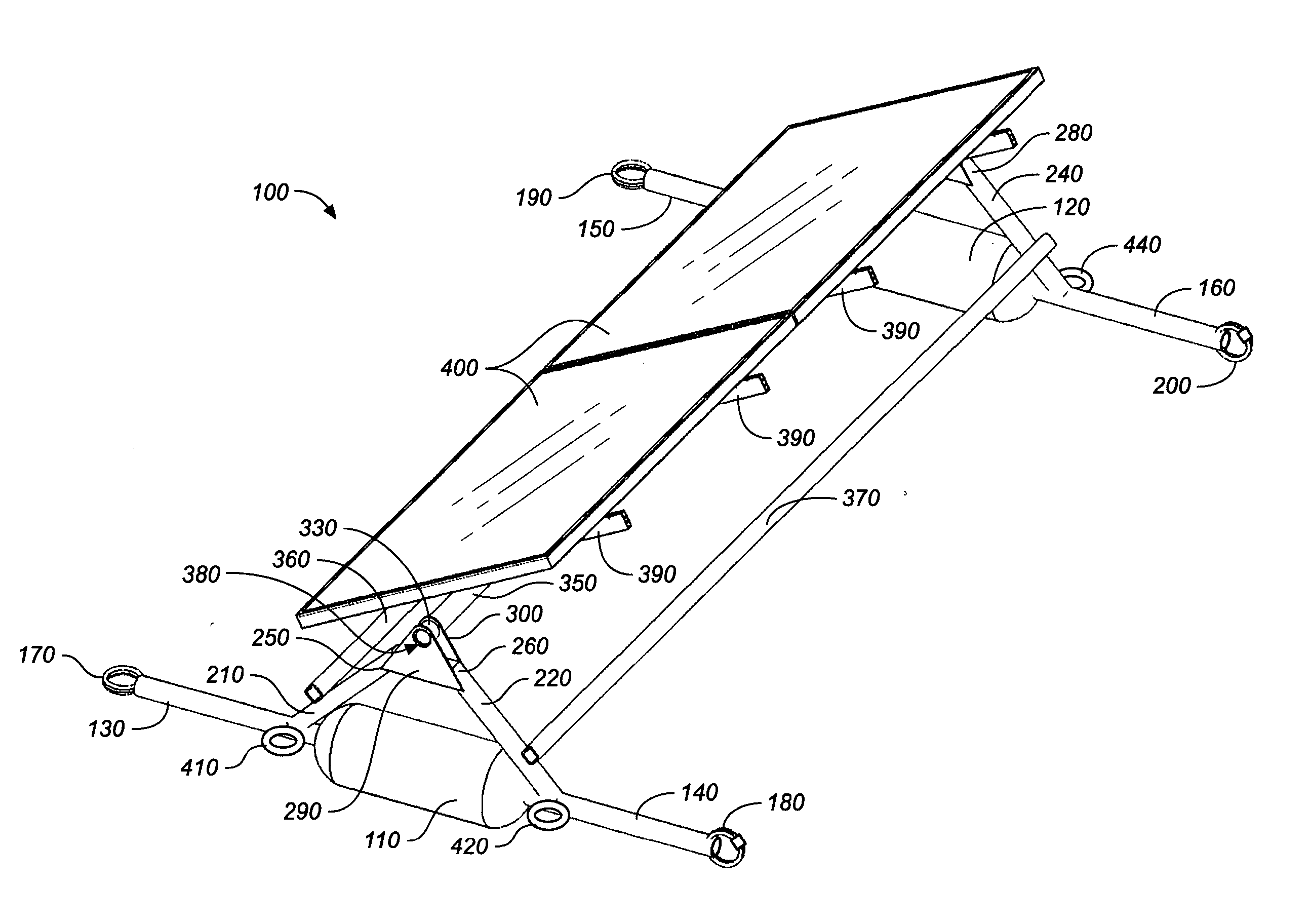
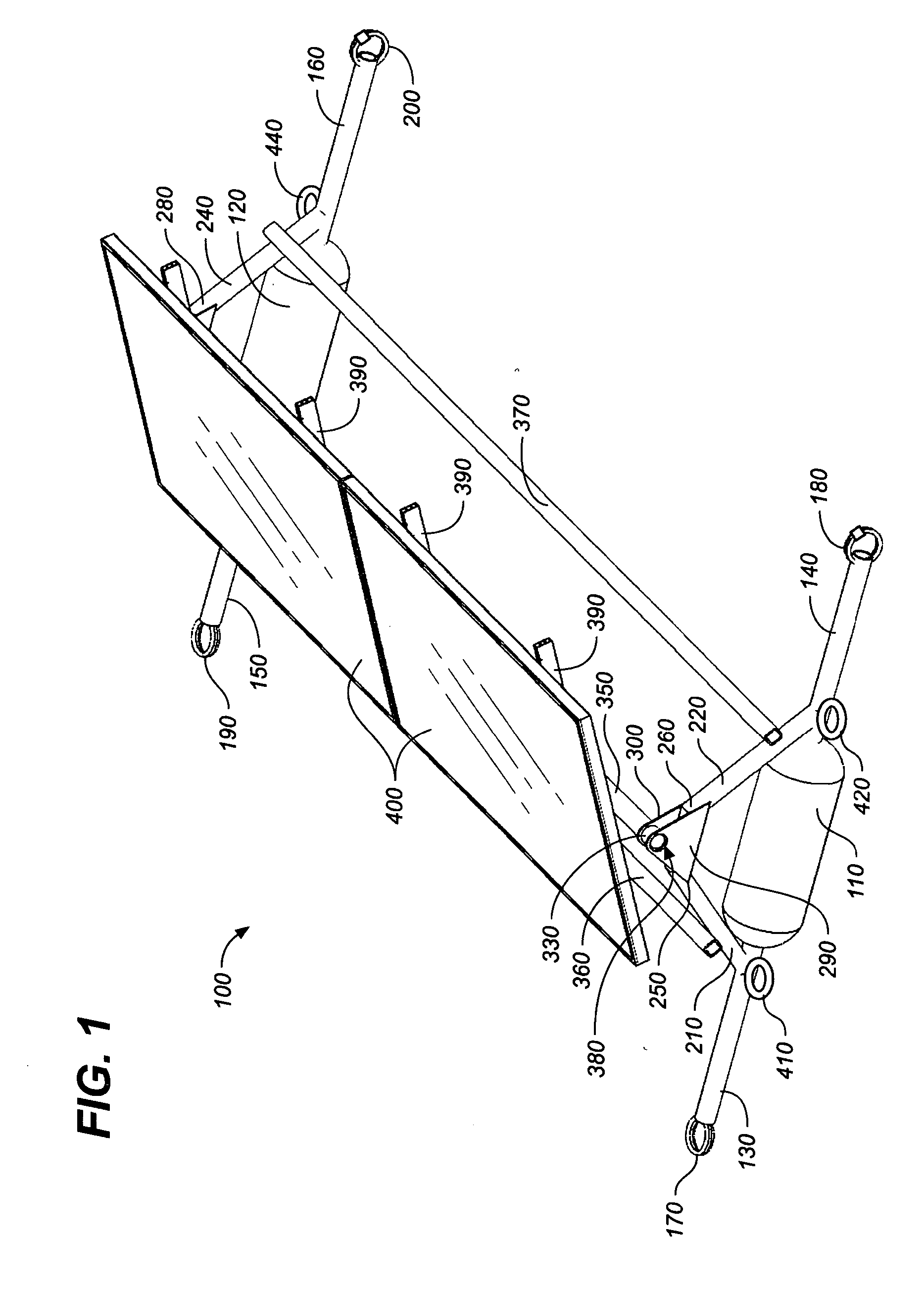
[0024] Referring to FIGS. 1 through 6, wherein like reference numerals refer to like components in the various views, there is illustrated therein a new and improved modular floating support structure for a solar panel array, generally denominated 100 herein.

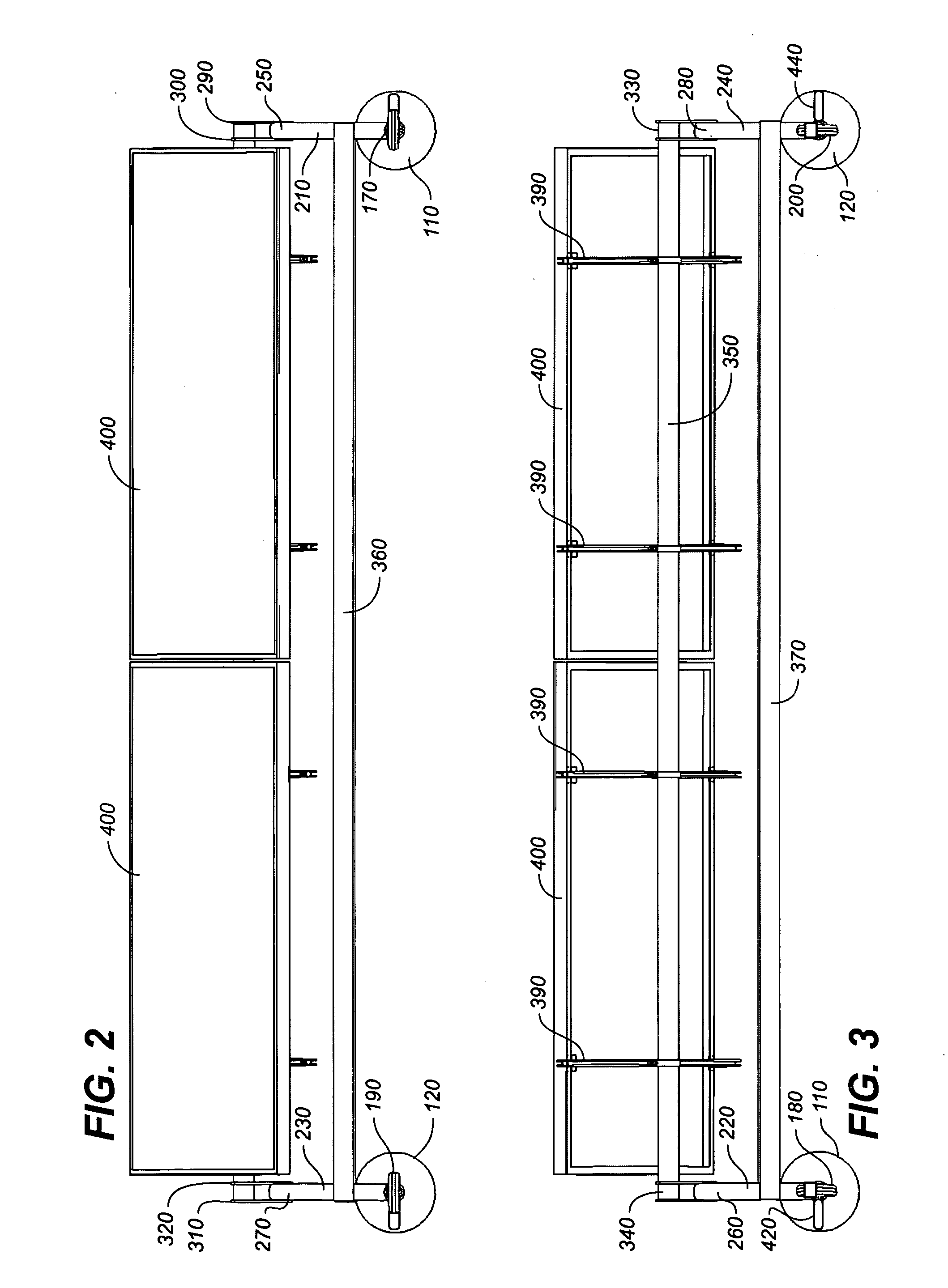
[0025]FIG. 1 is a perspective view of the modular support structure, while FIGS. 2, 3, and 4 are, respectively, front, back, and side elevation views of the module of FIG. 1. Collectively, these views show that this basic modular component of a floating array comprises first and second elongate flotation elements 110, 120, preferably substantially cylindrical pontoons, each having connector tubes 130, 140, and 150, 160, extending longitudinally from each respective end. Preferably the connector tubes are round in cross section, and their respective distal ends include front and rear connector rings, 170, 190, and 180, 200, respectively. The front connector rings 170, 190 are disposed generally perpendicular to the rear connecto...


PUM


Abstract

A floating support structure for a solar panel array having flotation elements and a tubular support structure disposed above the flotation elements for adjustably mounting at least one solar collector panel. Connector tubes and connector rings are provided near the base of the support structure for joining adjoining floating support structures.

Description

CROSS REFERENCE To RELATED APPLICATIONS [0001] The present application claims the benefit of the filing date of U.S. Provisional Patent Application Ser. No. 60 / 623,328, filed Oct. 29, 2004 (Oct. 29, 2004).STATEMENT REGARDING FEDERALLY SPONSORED RESEARCH OR DEVELOPMENT [0002] Not applicable. REFERENCE TO A MICROFICHE APPENDIX [0003] Not applicable. TECHNICAL FIELD [0004] The present invention relates generally to photovoltaic power systems, and more particularly to support structures for solar photovoltaic collector panels, and still more particularly to a floating support structure for a solar panel array. BACKGROUND INFORMATION AND DISCUSSION OF RELATED ART [0005] With a few exceptions, solar panel support structures are almost invariably adapted for installation of a solar panel on the ground or a rooftop. Notable exceptions include support frameworks for mounting solar panels on vehicles and boats, and more exotic uses may even call for an installation with no support framework, ...

Claims


Application Information

Patent Timeline
IPC IPC(8): H01L25/00
CPCF24J2/5239F24J2/5267H02S20/00Y02E10/47Y02E10/50F24J2/541H02S20/30F24S25/16F24S30/425F24S20/70
Inventor THOMPSON, DANIEL S.
Owner SPG SOLAR
Why Eureka
Try Eureka