
System and method for rapidly stopping a spinning table saw blade

a technology of detection system and blade, which is applied in the field of detection system and method for rapidly stopping a spinning saw blade, can solve the problems of destroying the saw blade, early and effective detection of the user's hand and cost, and severely restricting the flexibility of the machin

Inactive Publication Date: 2006-05-11
CHANG TYPE INDAL
View PDF99 Cites 71 Cited by
  • Summary
  • Abstract
  • Description
  • Claims
  • Application Information

AI Technical Summary

Problems solved by technology

All of the presently available systems and methods have one or more disadvantages in terms of convenience of use, early and effective detection of a user's hand and cost.
For instance, the system which employs a brake mechanism destroys the saw blade when used.
Additionally, employment of the three-in-one system severely limits the flexibility of the machine (e.g. user is limited to making through-cuts because the splitter sits higher than the blade, any partial cut such as a groove or a joint may not be done without removing the entire system).

Method used


Image

  • System and method for rapidly stopping a spinning table saw blade
  • System and method for rapidly stopping a spinning table saw blade
  • System and method for rapidly stopping a spinning table saw blade

Examples


Embodiment Construction

[0016] Reference will now be made in detail to the presently preferred embodiments of the invention, examples of which are illustrated in the accompanying drawings.

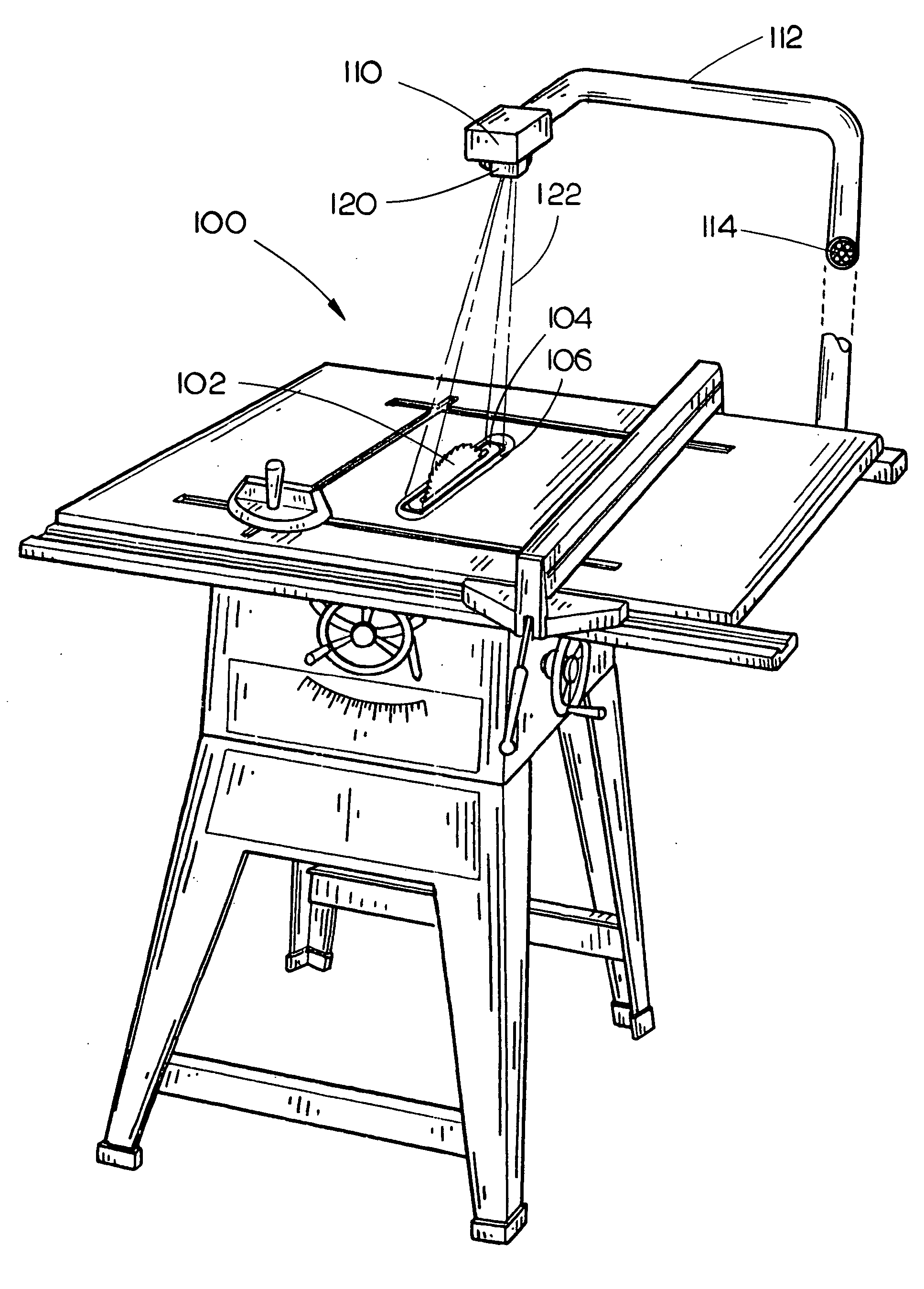
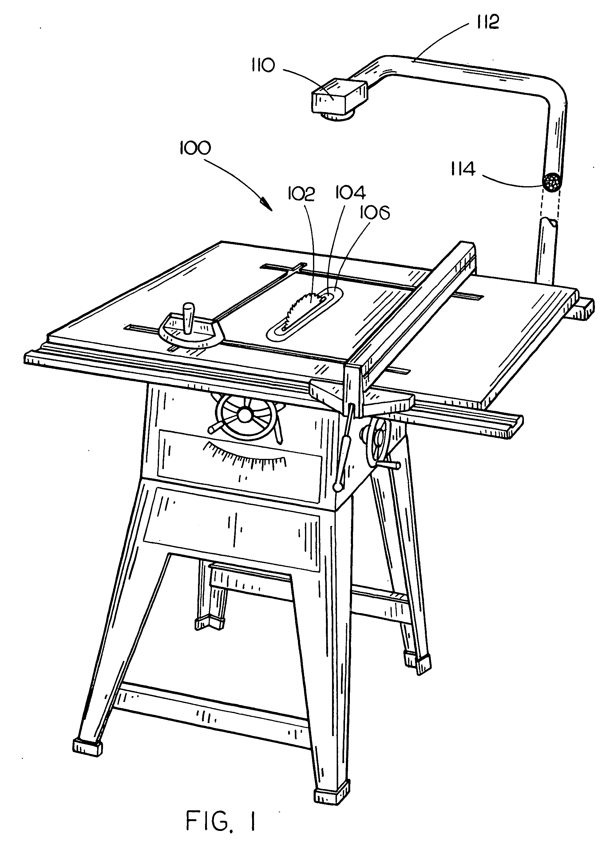
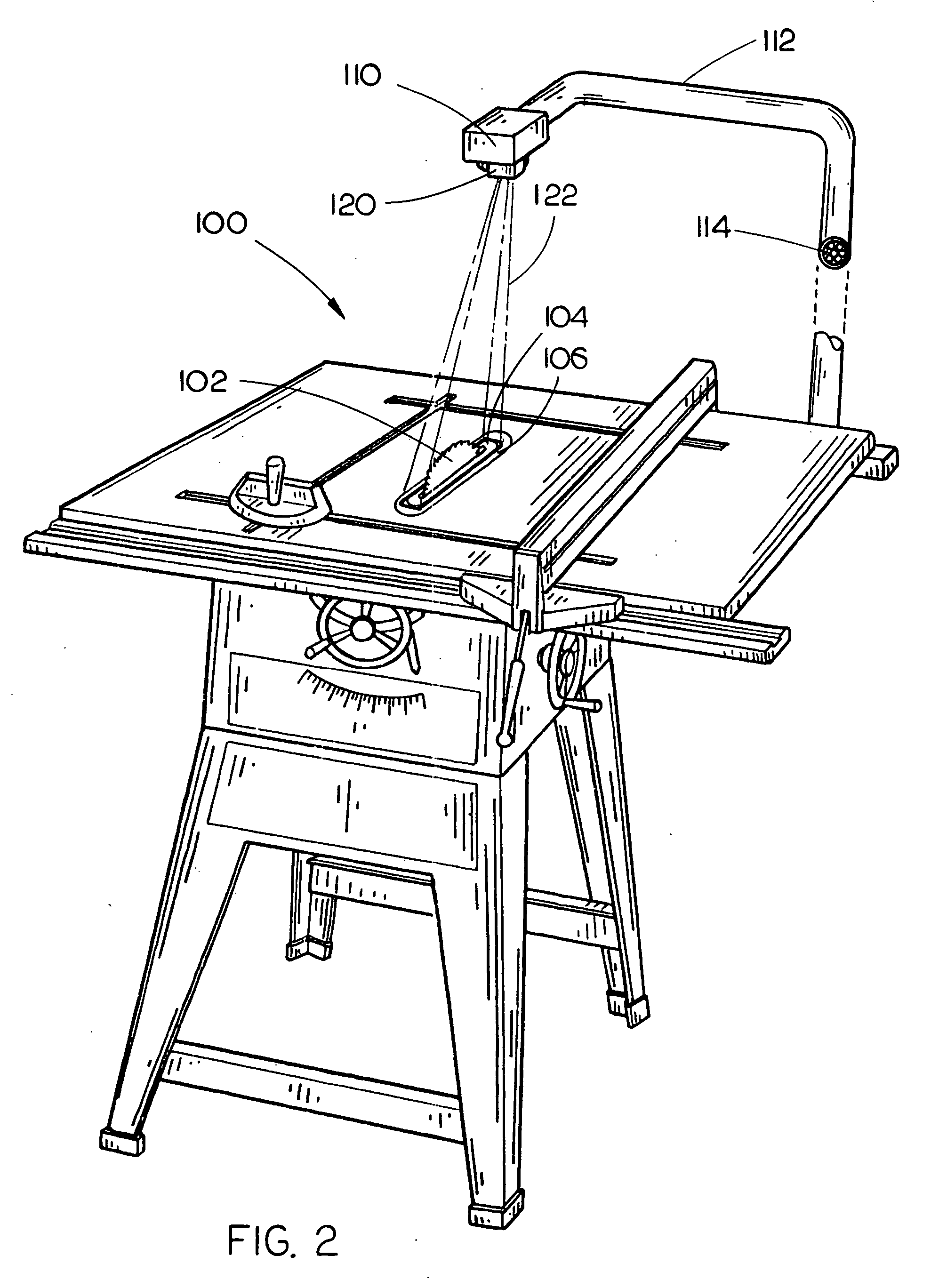
[0017] Referring in general to FIGS. 1-6, a detection system for rapidly stopping a spinning saw blade in response to input from a sensing device that detects possible contact of the blade with a user's hand is disclosed. In use, upon sensing a user's hand in a pre-defined zone, a sensing assembly signals a driving assembly to stop the rapidly spinning saw blade by driving a pin assembly through the saw blade and into a receiving block. In one embodiment, the detection system becomes activated prior to a user's hand making contact with the saw blade which is a major advantage over the prior art which requires such contact. Further, the detection system is positioned to allow an workspace on the table top surface to be unobstructed. In additional embodiments, the pin assembly is actuated by an explosive or detonation subs...


PUM

PropertyMeasurementUnit
Electrical resistanceaaaaaaaaaa
Shapeaaaaaaaaaa
Capacitanceaaaaaaaaaa

Abstract

A system for stopping a spinning table saw blade is comprised of a pin assembly disposed adjacent to a saw blade assembly for stopping a spinning saw blade. A receiving block is disposed on a side of the saw blade opposing the pin assembly for receiving the tip of the pin assembly. A driving assembly is coupled to the pin assembly for driving the pin assembly into the spinning saw blade into the receiving block. Finally, a sensing assembly is coupled to at least one of the saw blade assembly and the driving assembly for sensing encroachment of a user's hand in a pre-defined zone. In use, upon sensing a user's hand the sensing assembly signals the driving assembly to stop the spinning saw blade by driving the pin assembly through the saw blade and into the receiving block.

Description

CROSS-REFERENCE TO RELATED APPLICATIONS [0001] The present application is a continuation-in-part of U.S. patent application Ser. No. 10 / 836,132 filed Apr. 29, 2004 (Attorney Docket No. DEL 03-8-2), which in-turn claims priority under 35 USC §119(e) to provisional U.S. Application No. 60 / 466,199 filed Apr. 29, 2003 (Attorney Docket No. DEL 03-8-1). In addition, the present application claims priority entitled under 35 U.S.C. §119(e) to provisional U.S. Application No. 60 / 533,192 filed Dec. 30, 2003 (Attorney Docket No. DEL 03-47-1). Said U.S. patent application Ser. No. 10 / 836,132 and U.S. Provisional Patent Application 60 / 466,199 and 60 / 533,192 are herein incorporated by reference in their entirety.FIELD OF THE INVENTION [0002] The present invention relates generally to the field of saws and more particularly to a detection system and method for rapidly stopping a spinning saw blade. BACKGROUND OF THE INVENTION [0003] There exists a need for an effective method to rapidly stop a spi...

Claims


Application Information

Patent Timeline
IPC IPC(8): B26D1/00
CPCB23D59/001B27B5/38B27G19/02F16P3/148Y10S83/01F16P3/144F16P3/142F16P3/14Y10T83/04Y10T83/081Y10T83/773Y10T83/8863
Inventor KELLER, DAVID V.
Owner CHANG TYPE INDAL
Learn More