Mobility device

Inactive Publication Date: 2006-05-11
USHEROVICH BORIS
View PDF10 Cites 19 Cited by
  • Summary
  • Abstract
  • Description
  • Claims
  • Application Information

AI Technical Summary

Benefits of technology

[0009] In a first embodiment, the securement mechanism is configured to secure the mobility device to a manually operated wheel chair such that each of the drive members is in frictional contact with a rear wheel of the wheel chair. The securement mechanism can be configured to releasably secure the mobility device to the wheel chair. in one embodiment, the securement mechanism includes at least one bracket which is movable, e.g., pivotal, to move the drive members from a position contacting the rear wheels of a wheel chair to a position spaced from the rear wheels of a wheel chair. The at least one bracket may include a pair of br

Problems solved by technology

Known powered wheel chairs include a fairly complex drive system for driving the wheels of the wheel chair in response to operation of a set of hand controls or the like.
Known powered wheel chairs are substantially more costly than manually operated wheel chairs.
One problem associated with manually operated wheel chairs is that operation of the wheel chair is dependent on an occupant's strength.
Since many wheel chair occupants do not have the strength to operate a manually operated wheel chair, they are left with only two options: 1) bear the great expense of purchasing a powered wheel chair; or 2) give up the freedom of mobility.

Method used


Image

  • Mobility device
  • Mobility device
  • Mobility device

Examples


Embodiment Construction

[0014] Preferred embodiments of the presently disclosed mobility device will now be described in detail with reference to the drawings, in which like reference numerals designate identical or corresponding elements in each of the several views.

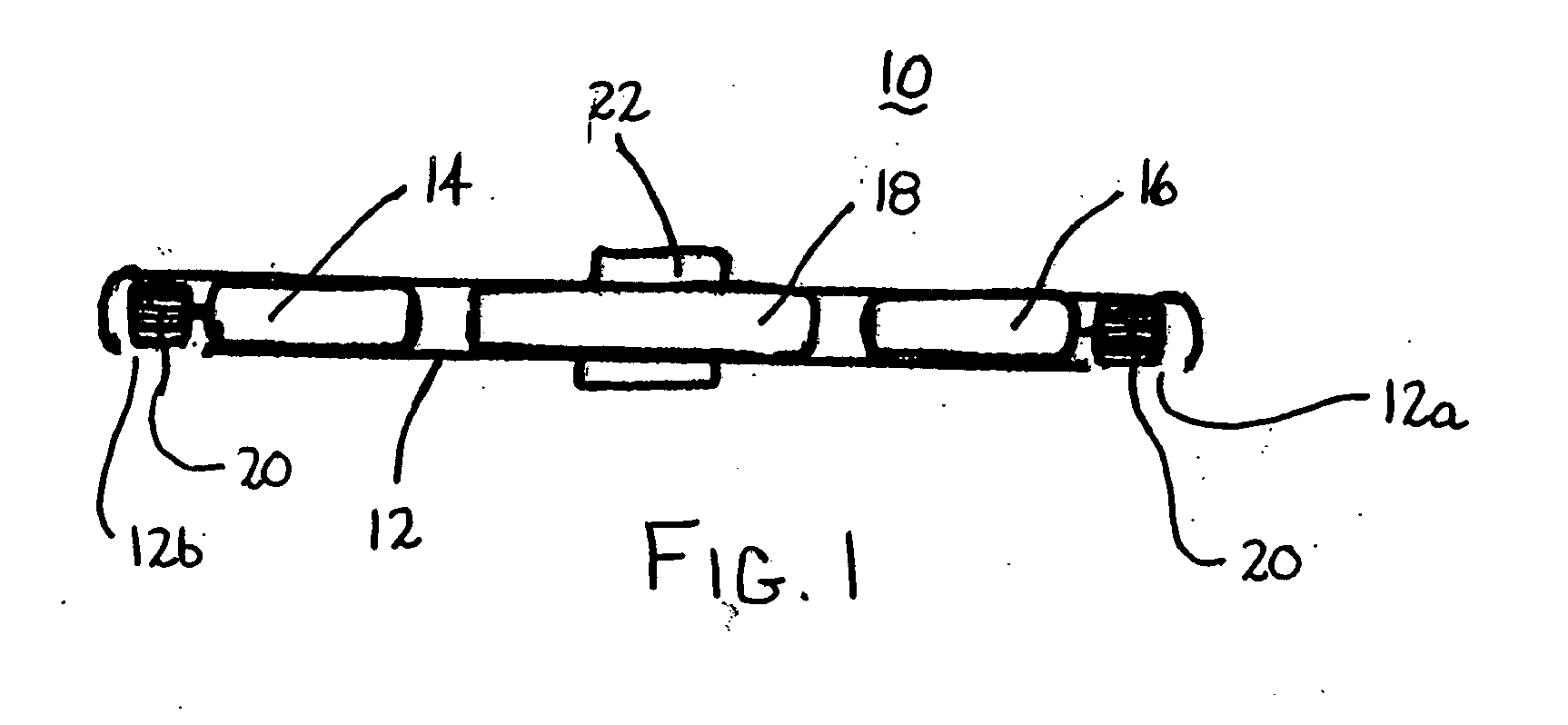
[0015]FIG. 1 illustrates one embodiment of the presently disclosed mobility device shown generally as 10. Mobility device 10 includes a housing 12 having a first opening 12a and a second opening 12b. Housing 12 is dimensioned to receive at least one, and preferably, a pair of drive motors 14 and 16. Housing 12 may be constructed from a metal or a plastic having the requisite strength requirement. Alternately, other materials of construction can be used to construct housing 12. In one preferred embodiment, a battery 18 is supported within housing 12 for powering drive motors 14 and 16. Preferably, motors 14 and 16 are reversible DC motors and battery 18 is a 12V rechargeable battery. Alternately, other known drive motors and power sources may ...


PUM


Abstract

A mobility device is provided for converting a manually powered wheel chair or stationary chair to a powered mobile chair. The mobility device includes a housing, a pair of independently and / or simultaneously operable reversible motors, and a pair of drive members. The drive members may be in the form of frictional contact members for driving the rear wheels of a wheel chair or drive wheels for supporting and driving a stationary chair. A control device can be provided to control operation of the drive motors, and thus, movement of the stationary or wheel chair. The mobility device may include one or more rechargeable batteries which may be supported internally or externally of the housing.

Description

[0001] This application claims priority from U.S. Provisional Application Ser. No. 60 / 625,613, filed on Nov. 5, 2004.BACKGROUND [0002] 1. Technical Field [0003] The present disclosure relates to a mobility device for use with an existing chair. More particularly, the present disclosure relates to a mobility device which can be attached to an existing wheel chair or stationary chair to convert the chair from a manually driven or stationary chair to a powered mobile chair. [0004] 2. Background of Related Art [0005] The use of wheel chairs including both powered and manually driven wheelchairs has been well known for a great number of years. Wheel chairs have been used to effect the transport of the injured, sick, aged or some combination thereof. Typically, known manually operated wheel chairs include two large rear wheels which can be grasped by an occupant and rotated to advance the chair. Known powered wheel chairs include a fairly complex drive system for driving the wheels of the...

Claims


Application Information

Patent Timeline
IPC IPC(8): B62M7/14
CPCA61G5/045A61G5/047A61G2005/1054A61G2203/14A61G5/1054
Inventor USHEROVICH, BORIS
Owner USHEROVICH BORIS
Why Eureka
Try Eureka