
Skateboard truck assembly

a technology for skateboards and trucks, applied in the field of skateboards, can solve the problems of reducing the resistance of the axle to pivot, affecting the stability of the skateboard, so as to prevent the wheel from slipping

Inactive Publication Date: 2006-05-11
CHMELAR ERIK VACLAV
View PDF29 Cites 40 Cited by
  • Summary
  • Abstract
  • Description
  • Claims
  • Application Information

AI Technical Summary

Benefits of technology

[0029] It is an object of the present invention to provide a skateboard truck assembly that prevents wheel bite.
[0030] It is an object of the present invention to provide a skateboard truck assembly wherein the maximum angle through which the hanger assembly can pivot relative to the skateboard platform is easily adjusted by the user.
[0031] It is an object of the present invention to provide a skateboard truck assembly wherein the maximum angle through which the hanger assembly can pivot relative to the skateboard platform is independent to its pivot sensitivity and therefore independent to the steering responsiveness of the skateboard.
[0032] It is an object of the present invention to provide a skateboard truck assembly that is inexpensive to manufacture.
[0033] It is an object of the present invention to provide a skateboard truck assembly that is easy to use.

Problems solved by technology

Likewise, loosening the kingpin nut decreases the resistance of the axle to pivot and makes the skateboard more willing to turn.
Although these prior art truck assemblies are capable of securing wheels to a vehicle such as a skateboard and permit turning thereof, they suffer from one or more disadvantageous properties.
Therefore, the above previously proposed truck assemblies that deviate significantly from the general shape and form of a typical skateboard truck assembly are highly undesired.
The remaining above previously proposed truck assemblies that do not deviate significantly from the general shape and form of a typical skateboard truck assembly have a design flaw that can result in an undesired ride characteristic called wheel bite.
Such an uneven distribution of weight can cause the hanger assembly to pivot through a great angle relative to the platform and cause the wheels to contact the platform, called wheel bite.
Wheel bite can cause the wheels to stop rotating and the skateboard to stop moving, and often causes the skateboarder to fall.
The only way to prevent wheel bite is to tighten the kingpin nut to sufficiently retard the pivoting action of the hanger assembly, but this inhibits the steering responsiveness of the skateboard and is therefore highly undesired.
Although U.S. Pat. No. 6,443,471 (Mullen) claims to solve wheel bite by providing a bushing with an annular flange, it still relies on the tightness or looseness of a kingpin nut to function and therefore affects the steering responsiveness of the skateboard.
Furthermore, because the device of U.S. Pat. No. 6,443,471 (Mullen) is comprised of a soft material, it cannot completely prevent wheel bite.

Method used


Image

  • Skateboard truck assembly
  • Skateboard truck assembly
  • Skateboard truck assembly

Examples


second embodiment

[0067]FIG. 10 shows the present invention, which generally comprises a c-shaped element 17, a wedge element 18, and a screw 19 that is engaged to the wedge element 18. FIG. 11a and FIG. 11b, which are cross-sectional views of the hanger 3 of a skateboard truck assembly 1 like that shown in FIG. 3 taken along the line C-C, show the device of FIG. 10 engaged to the hanger 3 in a first bore 20 that is defined partially in the part of the ring-shaped member 29 nearest the axle 4 for accepting the c-shaped element 17 and partially in the hanger 3 for accepting the wedge element 18, and a second bore 21 that is defined in the hanger 3 for accepting the screw 19. The c-shaped element 17 rests on a partial flange 32 that is defined in the ring-shaped member 29 and the wedge element 18 is engaged by the screw 19.

first embodiment

[0068]FIG. 11a shows the generally perpendicular position of the c-shaped element 17, the wedge element 18, and the screw 19 relative to the axis of the kingpin bolt 5 when the screw 19, whose head rests between a first flange 22 and a second flange 23 that are both defined in the second bore 21 of the hanger 3, is actuated such that the wedge element 18, to which it is engaged, is pushed towards the kingpin bolt 5, causing the c-shaped element 17 to close in towards the kingpin bolt 5. Likewise, FIG. 11b shows the position of the c-shaped element 17, the wedge element 18, and the screw 19 when the screw 19 is actuated such that the wedge element 18 is pulled away from the kingpin bolt 5, causing the c-shaped element 17 to open up away from the kingpin bolt 5. Similar to the present invention, the gap between the c-shaped element 17 and the kingpin bolt 5, determined by the position of the wedge element 18 relative to the c-shaped element 17, determines the maximum angle through whi...

third embodiment

[0070]FIG. 14 shows the present invention, which generally comprises an elongated element 26, which has a trapezoidal-shaped bore 27 defined therein, and a screw 19 engaged thereto. FIG. 15, which is a cross-sectional view of a skateboard truck assembly 1 like that shown in FIG. 2 taken along the line A-A, shows the device of FIG. 14 engaged to the hanger 3, which includes the axle 4, in a first bore 20 that is defined partially in the ring-shaped member 29 and partially in the hanger 3 for accepting the elongated element 26 and a second bore 21 that is defined in the hanger 3 for accepting the screw 19, both of which are generally perpendicular to the axis of the kingpin bolt 5.

[0071] Actuating the screw 19, whose head rests between a first flange 22 and a second flange 23, causes the elongated element 26 to move relative to the kingpin bolt 5, which is routed through the trapezoidal-shaped bore 27 defined in the elongated element 26, such that the kingpin bolt 5 can be positioned ...


PUM


Abstract

A truck assembly for a skateboard or the like that is configured to eliminate the undesired ride characteristic of wheel bite without sacrificing the turning responsiveness thereof and without deviating from the general shape and form of a typical skateboard truck. In the preferred embodiment of the invention each truck assembly includes an axle assembly with a ring-shaped member, disposed about a kingpin, that includes two threaded bores longitudinally oriented in the general plane of the ring-shaped member substantially parallel to the axis of the axle and on generally opposite sides of the kingpin, in each of which is positioned a bolt whose distance from the kingpin is determined by actuation of the bolt such that when the axle assembly pivots through an angle about the axis of the kingpin and causes one or more of the bolts to contact the kingpin, the contacting bolt or bolts resists any further pivoting of the axle assembly beyond that angle. In a further feature of the invention the kingpin is modified to define a flat edge along generally opposite sides thereof, each flat edge being adjacent to each bolt positioned within its respective threaded bore.

Description

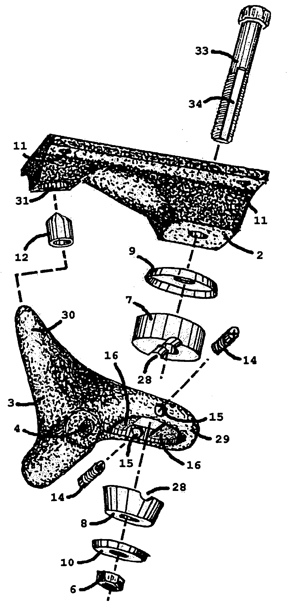
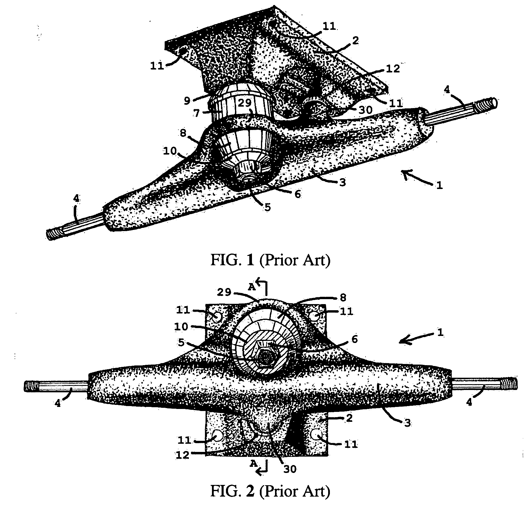
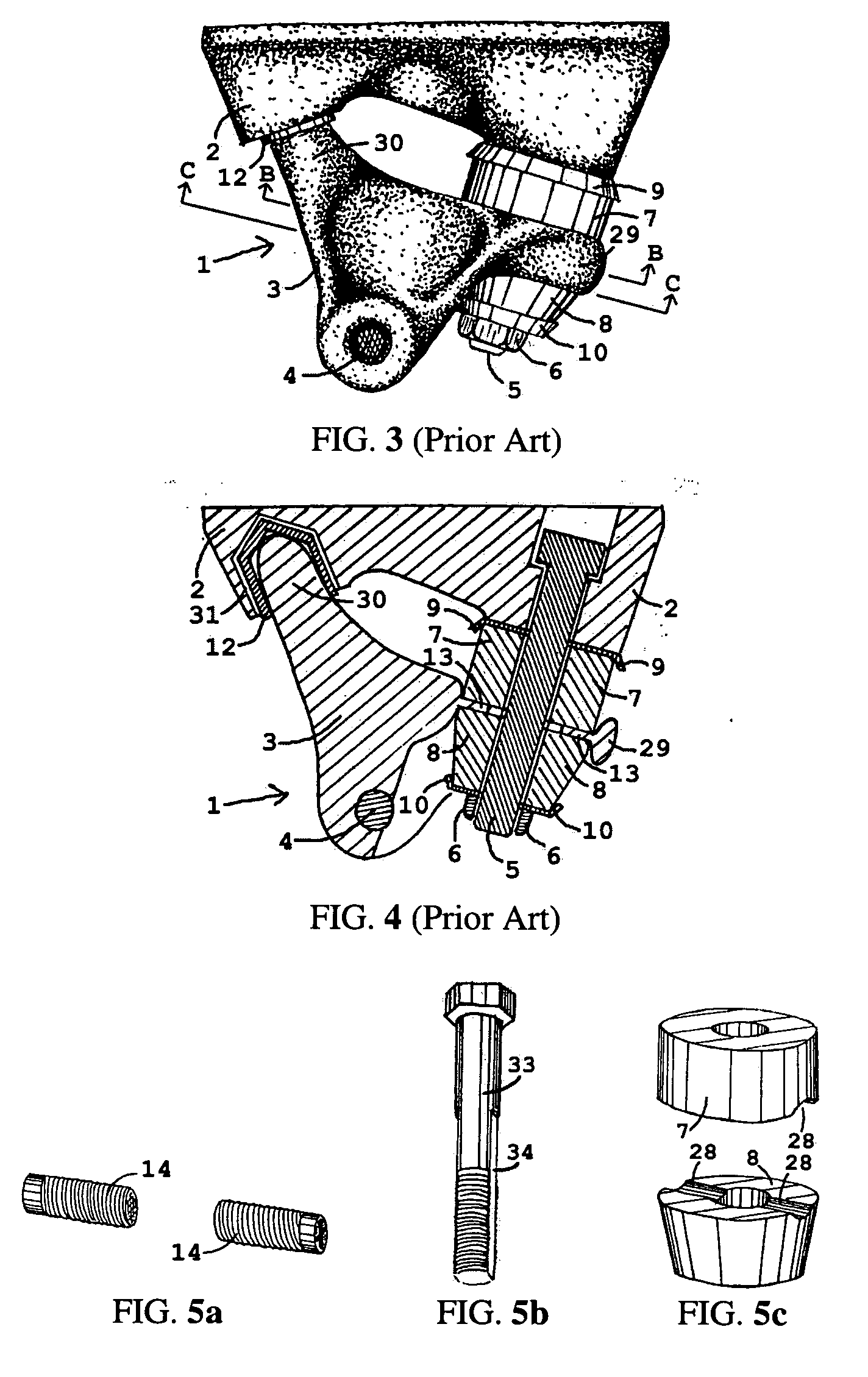
BACKGROUND OF THE INVENTION [0001] The present invention relates generally to vehicles that employ an axle or axle assembly that pivots relative to the vehicle to permit turning thereof and, more specifically, to a truck assembly that prevents the axle or axle assembly from pivoting beyond a specified angle relative to the vehicle. Such a truck assembly is of use for skateboards or other recreational vehicles to secure the wheels thereto. [0002] A skateboard typically comprises an elongated platform with a pair of truck assemblies secured at opposite ends to the underside of the platform. Each truck assembly typically comprises a base that is non-moveably secured to the platform and a hanger assembly, which includes an axle, that is moveably secured to the base by means of a kingpin bolt such that the hanger assembly can pivot along the axis of the kingpin bolt relative to the base and the skateboard platform. The hanger and base of a typical skateboard truck assembly is formed of a...

Claims


Application Information

Patent Timeline
IPC IPC(8): B62M1/00
CPCA63C17/0093A63C17/01A63C17/012A63C17/015
Inventor CHMELAR, ERIK VACLAV
Owner CHMELAR ERIK VACLAV
Learn More