Antenna for a plurality of bands

a technology for antennas and bands, applied in the field of antennas for multiple bands, can solve the problems of inability to operate in multiple frequency bands, difficult to reduce the size and weight of mobile communication devices,

Inactive Publication Date: 2006-05-11
YOKOWO CO LTD
View PDF9 Cites 137 Cited by
  • Summary
  • Abstract
  • Description
  • Claims
  • Application Information

AI Technical Summary

Benefits of technology

[0012] By employing a single antenna element and using the switches inserted between the intermediate points and the other end of the antenna element and the ground terminal, a desired number of frequency bands can be set. Thus, this antenna is favorable as a small antenna for mobile communication and operation in multiple frequency bands.

Problems solved by technology

However, any antenna of the above prior art is designed to operate in a single frequency band and cannot operate in multiple frequency bands.
Hence, it is difficult to reduce the size and weight of a mobile communication device by using any of the above prior art antennas.

Method used


Image

  • Antenna for a plurality of bands
  • Antenna for a plurality of bands
  • Antenna for a plurality of bands

Examples


first embodiment

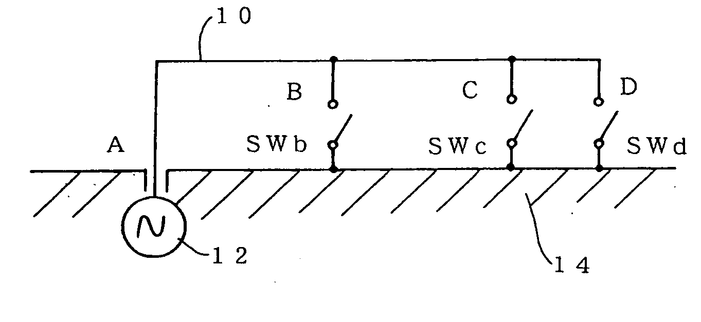
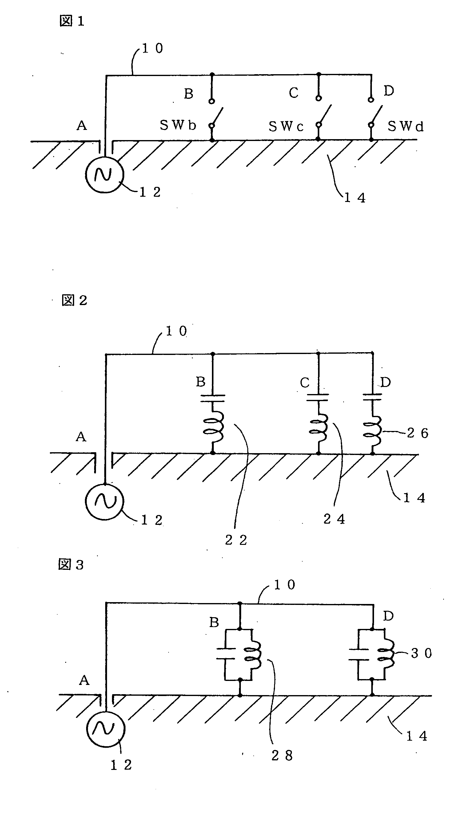
[0048] In the above-described antenna structure, when the switches SWb and SWc are open and only the switch SWd is closed, the antenna with the electrical length from the point A to the point D on the antenna element 10 is formed and functions as the antenna resonating with the third frequency band f3, as is the case for the prior art antenna shown in FIG. 26. Similarly, when the switches SWb and SWd are open and only the switch SWc is closed, the antenna with the electrical length from the point A to the point C on the antenna element 10 is formed and functions as the antenna resonating with the second frequency band f2. When the SWc and SWd are open and only the switch SWb is closed, the antenna functions as the one resonating with the first frequency band f1.

[0049] As described above, the first embodiment of the antenna for multiple bands of the present embodiment employs the single antenna element 10, which is preferable for size and weight reduction purposes. By providing as ma...

eighth embodiment

[0063] Moreover, the present invention will be described with reference to FIGS. 15 through 20

[0064]FIG. 15 is an outside perspective view of a concrete example of an antenna for multiple bands of the present invention on the assumption that the antenna is used in a mobile phone. FIG. 16 is a structural diagram of the antenna for multiple bands shown in FIG. 15. FIG. 17 shows a VSWR (voltage standing wave ratio) characteristic graph when SW1 is open and SW2 is closed in the antenna for multiple bands shown in FIG. 16. FIG. 18 shows a Smith chart when SW1 is open and SW2 is closed in the antenna for multiple bands shown in FIG. 16. FIG. 19 shows a VSWR characteristic graph when SW1 is closed and SW2 is open in the antenna for multiple bands shown in FIG. 16. FIG. 20 shows a Smith chart when SW1 is closed and SW2 is open in the antenna for multiple bands shown in FIG. 16.

[0065] In FIG. 15, the ground conductor 14 is a rectangle with a short side of 40 mm and a long side of 100 mm and...


PUM


Abstract

The present invention provides an antenna for multiple bands employing a single antenna element 10, capable of operating in multiple frequency bands, and ideal for size reduction purposes. One end A of an antenna element 10 is electrically connected to a feeding point 12 and intermediate points B and C and the other end thereof is electrically connected via switches SWb, SWc, and SWd to a ground conductor 14. The electrical lengths of the antenna element 10 from the terminal to the intermediate points B and C plus connection lines from these points via the switches SWb and SWc to the ground conductor 14 and the electrical length from the one end A to the other end D plus a connection line from the other end via the switch SWd to the ground conductor 14 are set to be capable of resonating different desired frequency bands. By closing one of the switches SWb, SWc, and SWd, one of the desired frequencies can be selected and the antenna can resonate with that frequency. Thus, the antenna employing the single antenna element 10 can operate in multiple frequency bands.

Description

TECHNICAL FIELD [0001] The present invention relates to an antenna for multiple bands, employing a single antenna element adapted so it can operate in multiple frequency bands. BACKGROUND ART [0002] Recent mobile communication has developed rapidly. Among others, mobile phones have proliferated outstandingly and improvements have been made to reduce their size and weight significantly. According to mobile phone standards, two particular frequency bands are used respectively in different regions: in Japan, a 800 MHz band and a 1.5 GHz band for Personal Digital Cellular (PDC); in Europe, a 900 MHz band and a 1.9 GHz band for Global System for Mobile Communications (GSM); and in U.S., a 800 MHz band for Advanced Mobile Phone System (AMPS) and a 1.9 GHz band for Personal Communications System (PCS). Moreover, communication systems such as Global Positioning System (GPS) using 1.5 GHz, Bluetooth using a 2.4 GHz band, and International Mobile Telecommunications (IMT) 2000 using a 2 GHz ba...

Claims


Application Information

Patent Timeline
Patent Type & Authority Applications(United States)
IPC IPC(8): H01Q1/38H01Q1/24H01Q1/36H01Q5/00H01Q5/10H01Q9/14H01Q9/42
CPCH01Q1/243H01Q1/36H01Q9/14H01Q9/42H01Q5/10H01Q1/24H01Q9/30
Inventor OSHIYAMA, TADASHIMIZUNO, HIROTOSHISUZUKI, YUSUKE
Owner YOKOWO CO LTD
Why Eureka
Try Eureka