Fluorescent tubes in orthogonal array backlight module

Inactive Publication Date: 2006-05-11
K-BRIDGE ELECTRONICS CO LTD
View PDF4 Cites 11 Cited by
  • Summary
  • Abstract
  • Description
  • Claims
  • Application Information

AI Technical Summary

Benefits of technology

[0006] The primary purpose of the present invention is to provide an improved structure for those multiple fluorescent tubes in an orthogonal array backlight module that allows easy assembly and effectively eliminates the flaw of inconsistent luminance observed with the prior art when longer fluorescent tubes are installed. To achieve the purpose, shorter fluorescent tubes are used, and a saddle is provide

Problems solved by technology

However, when the further increase of the length of each individual fluorescent tube 20 is required, problems including difficulties both in the manufacturing and the assembly of the longer fluorescent tube emerge.
The even

Method used


Image

  • Fluorescent tubes in orthogonal array backlight module
  • Fluorescent tubes in orthogonal array backlight module
  • Fluorescent tubes in orthogonal array backlight module

Examples


Example

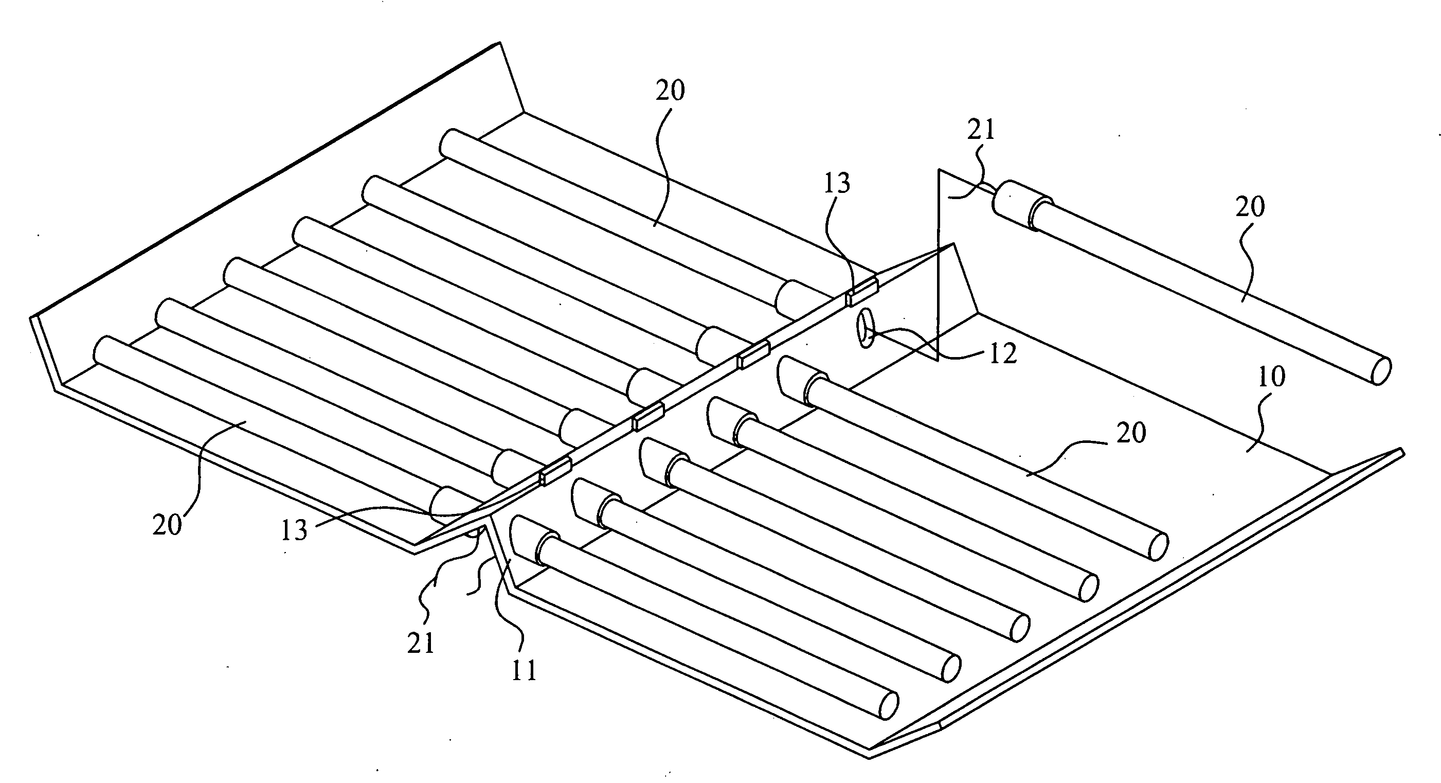
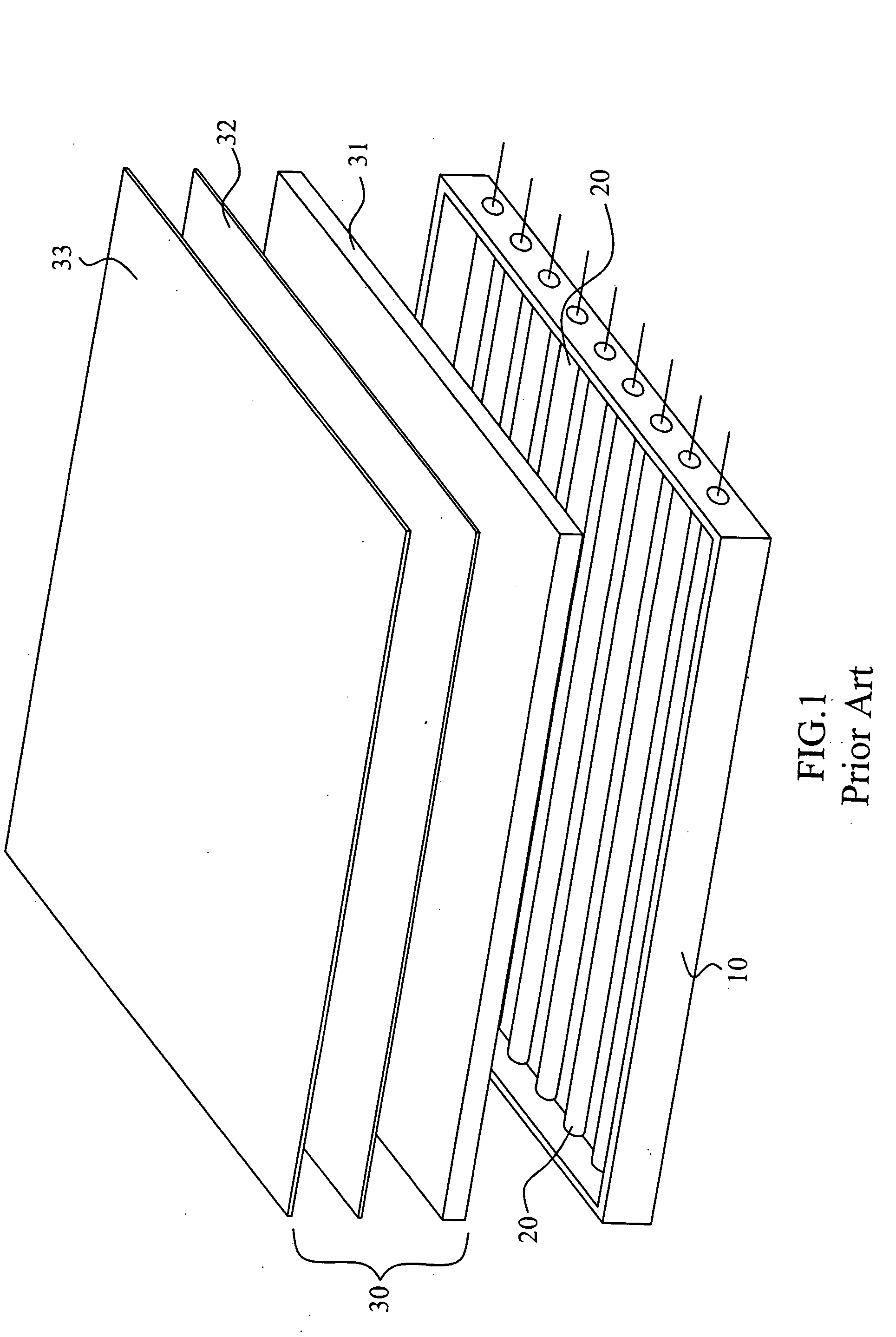
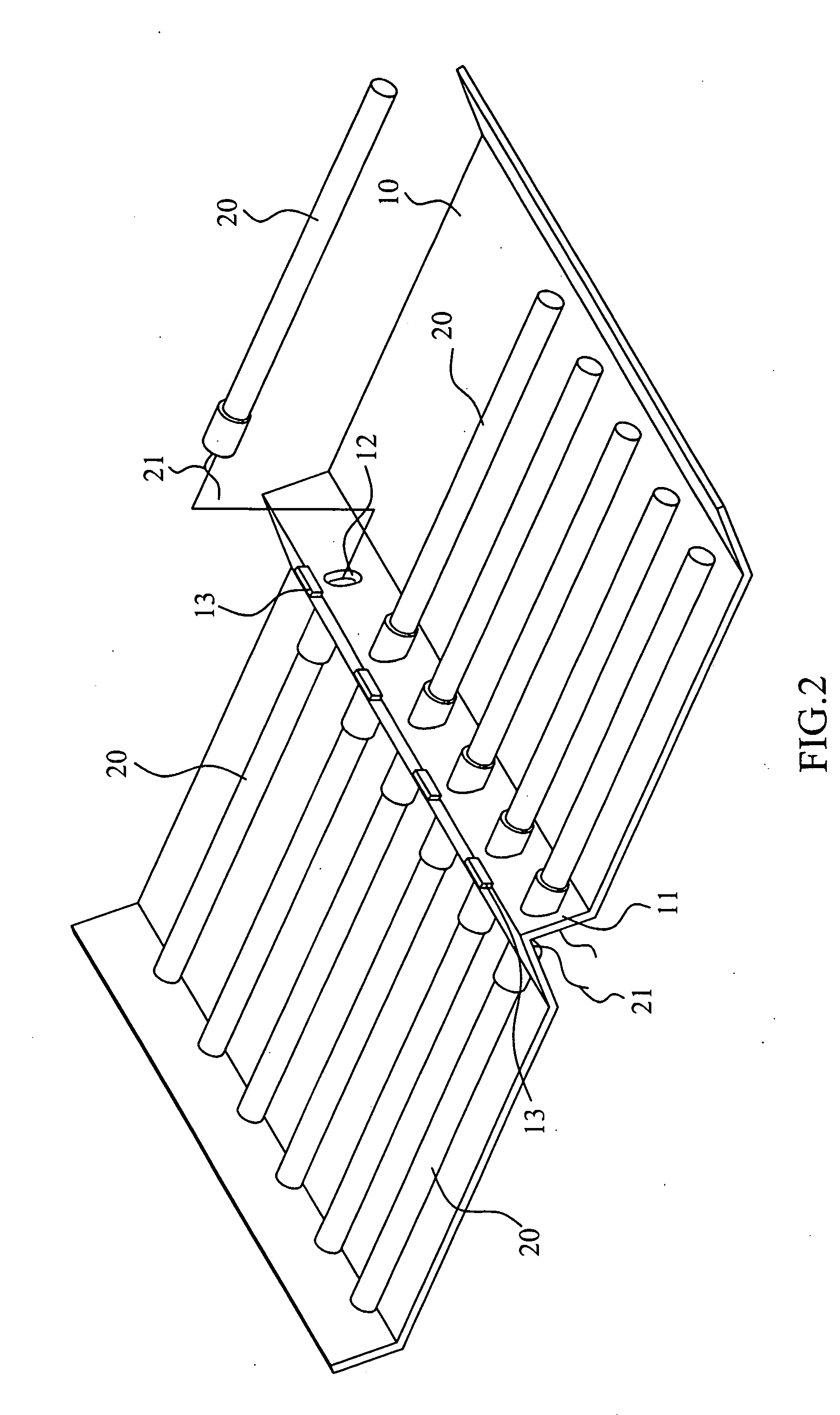
[0016] Referring to FIGS. 2 and 3, a preferred embodiment of the present invention is essentially comprised of an orthogonal array backlight module including multiple fluorescent tubes provided inside a light box and a display panel combined with a diffuser plate, an optical film, and a liquid crystal panel. Wherein, those fluorescent tubes 20 are paved of equal quantity on both wings in the light box 10. Given with the same size of the backlight module as that of the prior art, each fluorescent tube 20 is significantly shorter to permit easier assembly and to effectively avoid the flaw of being vulnerable to inconsistent distribution of luminance as observed with the prior art in the case longer fluorescent tubes are installed.

[0017] A saddle 11 is provided at the central line on the base of the light box 10 to define both wings in equal width. One end of each fluorescent tube 20 is fixed to a slope of the saddle 11 to serve as the adaptation end of an electrode 21 of the tube 20....


PUM


Abstract

An orthogonal array backlight module includes multiple fluorescent tubes paved on both inner sides of a light box, and a display panel comprised of diffuser plate, optical film and liquid crystal panel being provide on the top of the light box; and each fluorescent tube being significantly shorter than that of the prior art of same size to effectively provide consistent luminance and allow easier assembly.

Description

BACKGROUND OF THE INVENTION [0001] (a) Field of the Invention [0002] The present invention is related to an orthogonal array backlight module lamp set, and more particularly, to one allows easier assembly and more consistent luminance by significantly shorter fluorescent tubes than those in any other backlight module of the same size. [0003] (b) Description of the Prior Art [0004] As illustrated in FIG. 1 of the accompanying drawings for an exploded view of an orthogonal array backlight module of the prior art applied in a LCD, multiple fluorescent tubes 20 are paved in a light box 10. A display panel 30 comprised of a diffuser plate 31, an optical film 32, and a liquid crystal panel 33 covers up an opening disposed on the top of the light box 10. Inner layer of the light box 10 is reflective to project lights from all the fluorescent tubes 20 towards the display panel 30. The display results of the entire backlight module are achieved by the lights projected from those fluorescent ...

Claims


Application Information

Patent Timeline
IPC IPC(8): F21V7/04
CPCG02F1/133604G02F1/133608
Inventor TSENG, WEN-PAOCHIANG, HSIN-CHIEN
Owner K-BRIDGE ELECTRONICS CO LTD
Why Eureka
Try Eureka