Surgical fastening system

a surgical and fastening technology, applied in the field of surgical fasteners, can solve the problems of increasing the time required for suturing process, increasing the overall surgical process, and requiring considerable skill and dexterity for suturing techniques, so as to improve the ability of surgeons to deploy

Inactive Publication Date: 2006-05-11
LAUFER MICHAEL D +1
View PDF21 Cites 1388 Cited by
  • Summary
  • Abstract
  • Description
  • Claims
  • Application Information

AI Technical Summary

Benefits of technology

[0012] The inventive devices are especially suited for advancement via a minimally invasive technique by providing features which improve the ability of the surgeon to deploy the fastener with accuracy and effectuate a proper seal with the fastener. The minimally invasive technique also may allow for visual inspection of the placement of the anchor.

Problems solved by technology

One undesirable aspect of manual suturing is that the suturing process adds time to the overall surgical process.
In addition, suturing techniques requires considerable skill and dexterity especially when tying knots in the suture or otherwise manipulating the suture.
The ability of a medical practitioner to manipulate a suture as well as knot the ends of the suture are further complicated when the site is not directly accessible to the practitioner.
In such cases, even if the complexity of suturing does not prevent the procedure from being completed in a minimally invasive manner, the length of the procedure is likely to increase.
Conventional fasteners do not easily lend themselves for use in minimally invasive surgical procedure.
As one example, the complexity of the known fastener-delivery devices requires devices with large profiles and limited flexibility further thereby limiting the potential for such devices to access remote locations.
Conventional surgical fasteners, especially, “I-shaped” or “H-shaped” fasteners are unsuitable for remote procedures due to their complex deployment mechanisms and inability to navigate tortuous pathways using access devices commonly used for minimally invasive procedures (e.g., catheters, introducer devices, scope-type devices such as endoscopes, bronchoscopes, colonoscopies, etc.).

Method used


Image

  • Surgical fastening system
  • Surgical fastening system
  • Surgical fastening system

Examples


Embodiment Construction

[0025] The following illustrations are provided as variations of the present invention. It should be understood that there are many combinations of the present invention and that figures illustrating all variations of the invention would be numerous. Therefore, the invention is intended to include combinations of aspects and features of the illustrated embodiments, or combinations of the specific embodiments themselves.

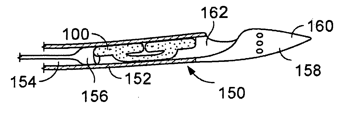
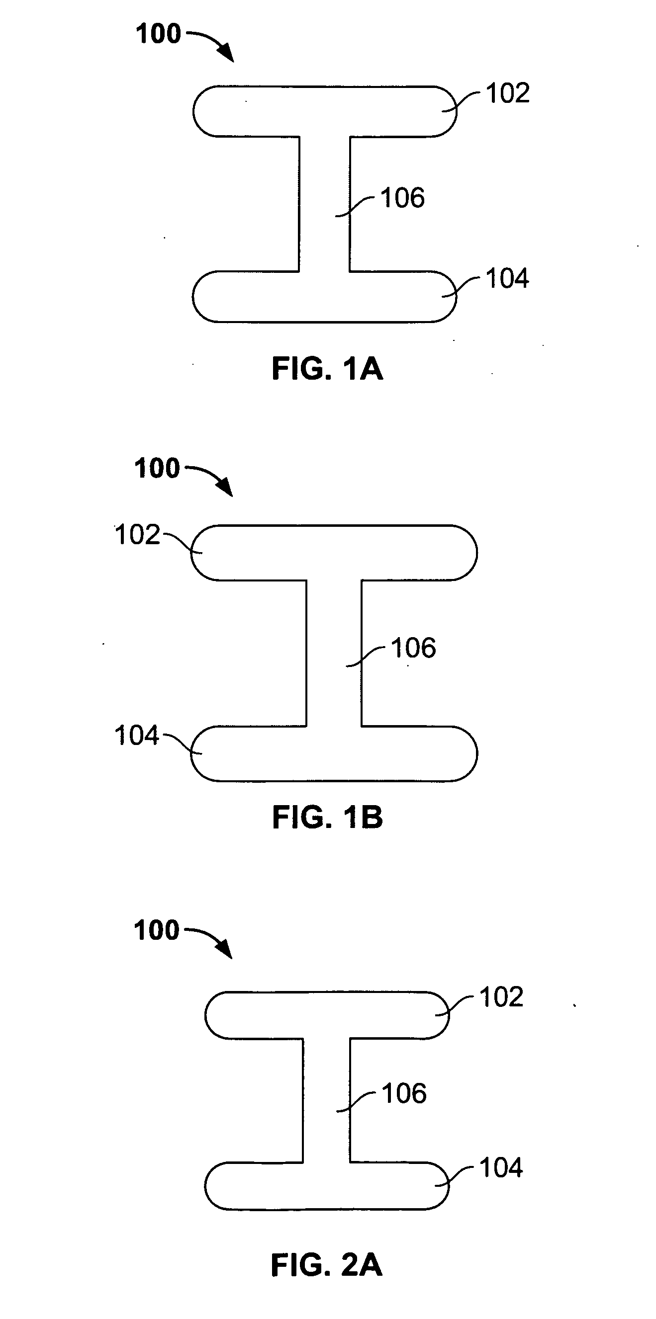
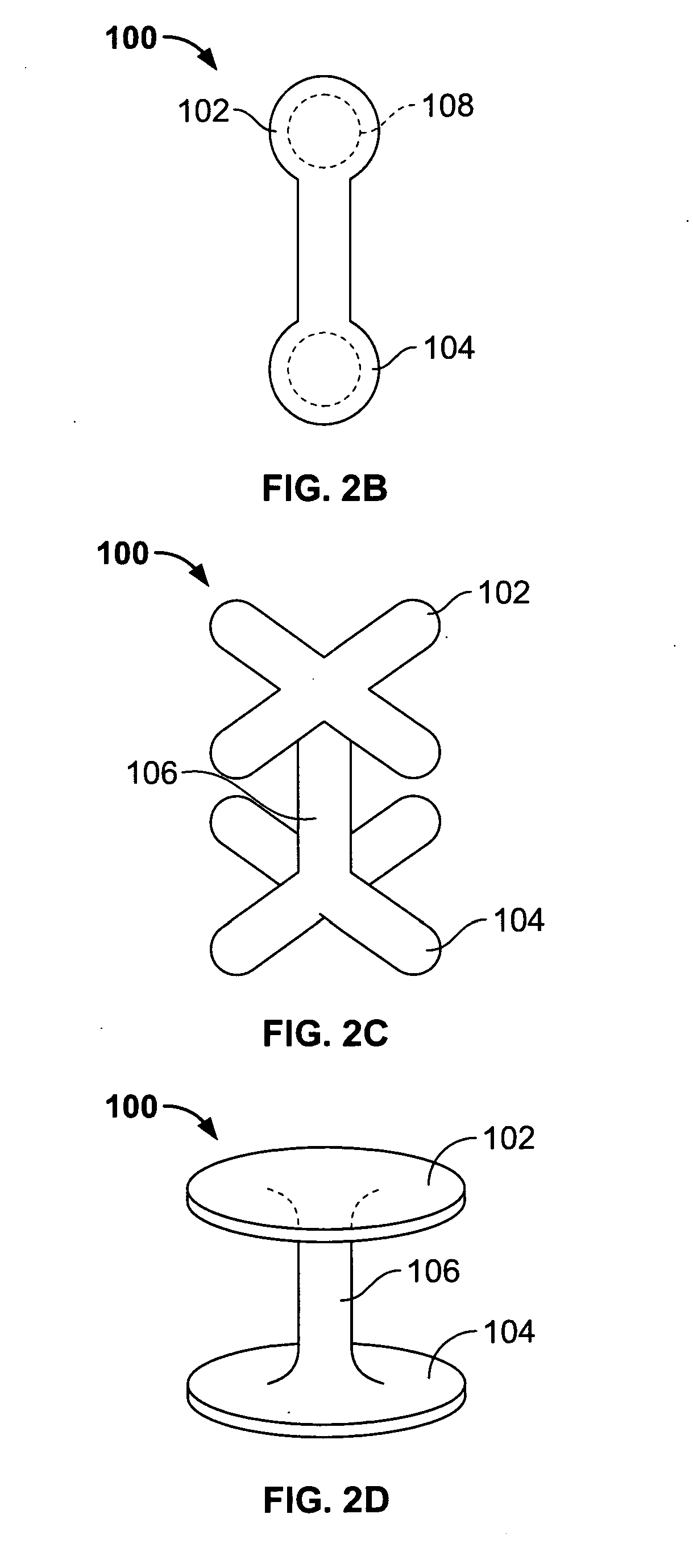
[0026]FIGS. 1A-1B, illustrate a side view of a basic variation of the inventive fastener 100. As seen in FIG. 1A, the fastener 100 includes a first anchor member 102 and a second anchor member 104 and a connecting portion 106 separating the two anchor members 102104. The “I-type” fastener shape illustrated in FIGS. 1A-1B is merely for illustrative purposes. Naturally, the anchor portions 102104 may have a variety of shapes, cross-sections, and configuration as discussed herein. However, the anchor portions 102104 will generally have a shape that allows for retention ...


PUM


Abstract

Devices and systems related to surgical fasteners and more specifically to surgical fasteners suitable for use in both open procedures, and minimally or less invasive procedures where the operative site is remote from the surgeon.

Description

CROSS-REFERENCE TO RELATED APPLICATIONS [0001] The present invention is a continuation of U.S. patent application Ser. No. 10 / 798,018 filed on Mar. 11, 2004, the entirety of which is incorporated by reference.FIELD OF THE INVENTION [0002] The present invention relates to surgical fasteners and more specifically to surgical fasteners suitable for use in both open procedures, and minimally or less invasive procedures where the operative or surgical site is not directly accessible by the surgeon. BACKGROUND OF THE INVENTION [0003] Surgical fasteners are known to be an alternative to traditional suturing techniques for procedures involving tissue closure, connection, or repair. One undesirable aspect of manual suturing is that the suturing process adds time to the overall surgical process. Moreover, manual suturing often requires that the operative area is readily accessible so that the medical practitioner can manipulate the suture and associated needle through both sides of the tissue...

Claims


Application Information

Patent Timeline
Patent Type & Authority Applications(United States)
IPC IPC(8): A61B17/10A61B17/00A61B17/04A61B17/08A61B19/00
CPCA61B17/10A61B2017/00004A61B2017/003A61B2017/00535A61B2017/00858A61B2017/00898A61B2017/0409A61B2017/0417A61B2017/0419A61B2017/0443A61B2019/307A61B2090/037
Inventor LAUFER, MICHAEL D.BAGADE, SANJAY S.
Owner LAUFER MICHAEL D
Why Eureka
Try Eureka