
Rotary hinge for rotationally coupling image capturing device with display panel

Inactive Publication Date: 2006-05-25
SKANHEX TECH
View PDF13 Cites 16 Cited by
  • Summary
  • Abstract
  • Description
  • Claims
  • Application Information

AI Technical Summary

Benefits of technology

[0008] In the above rotary hinge, the first ratchet wheel moves reciprocally and axially along the first pivot when the first pivot is rotated with the first protrusions moving on the second protrusions or moving to the region between the second protrusions. Because the first protrusions have a sharp tip, the first ratchet wheel can be automatically rotated to a stable condition that the second protrusions are positioned at the lowest region between the first protrusions. Therefore, rotating the second device relative to the first device can be automatically stopped at some predetermined angles dependent on where the first protrusions are positioned on the first ratchet wheel. The action between the first and second ratchet wheels as the second device is rotated about the first pivot relative to the first device will provide a click feeling to the user.
[0010] In the above rotary hinge, the protrusions of the second plate can be rotated over the first plate in response to the rotation of the pivot, or can be inserted into at least one of the angular positioning holes of the first plate. Therefore, rotation of the second device about the second pivot can be stopped as the protrusion of the second plate is inserted into the angular positioning holes and can be stopped at some predetermined angles dependent on where the angular positioning holes are positioned in the first plate. As the second device rotates about the second pivot, the action between the first and second plates will provide a click feeling to the user.
[0012] In the above rotary hinge, the first plate may comprise a disk spring, for example. The protrusions of the first plate can be rotated over the second plate in response to the rotation of the pivot, or can be inserted into at least one of the angular positioning holes of the second plate. Therefore, rotation of the second device about the second pivot can be stopped as the protrusion of the first plate is inserted into the angular positioning holes and can be stopped at some predetermined angles dependent on where the angular positioning holes are positioned in the second plate. As the second device rotates about the second pivot, the action between the first and second plates will provide a click feeling to the user.

Problems solved by technology

The angle between the display panel and the image-capturing device provided by the aforementioned rotary hinge is maximized at only 90 degrees, that is not enough for a user to comfortably watch the screen on the display panel during shooting pictures.

Method used


Image

  • Rotary hinge for rotationally coupling image capturing device with display panel
  • Rotary hinge for rotationally coupling image capturing device with display panel
  • Rotary hinge for rotationally coupling image capturing device with display panel

Examples


first embodiment

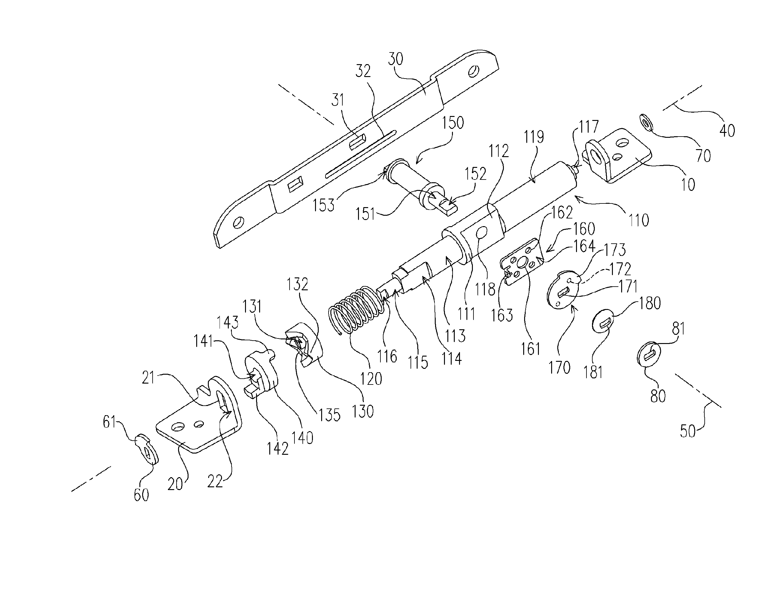
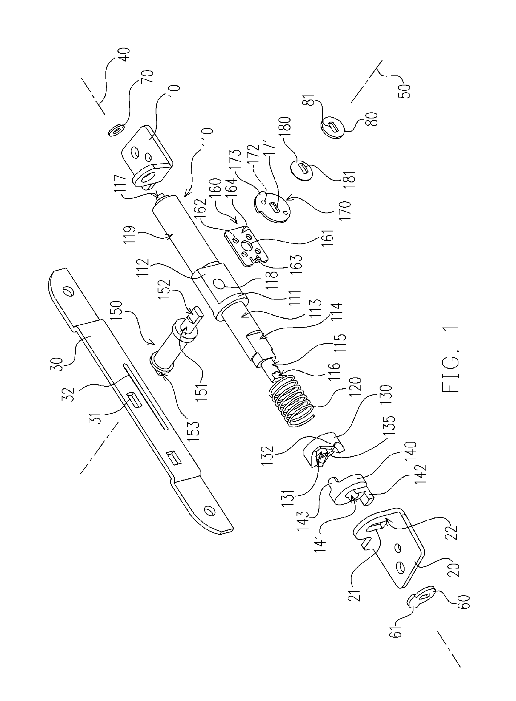
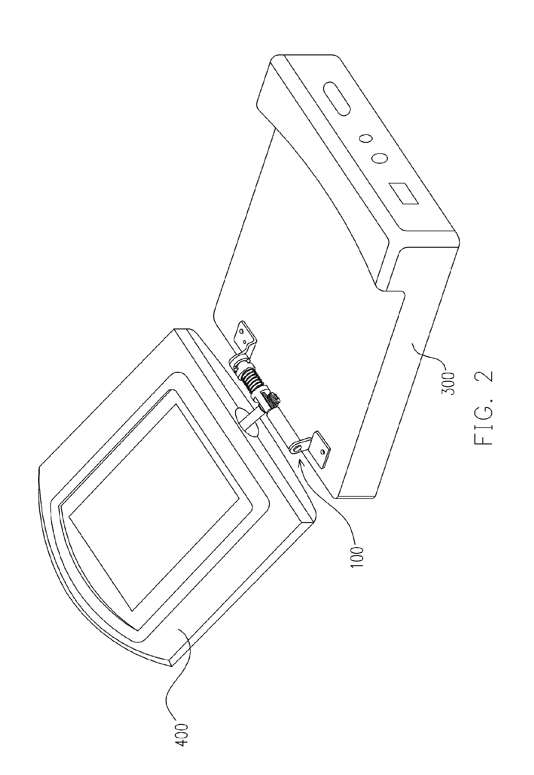
[0024]FIG. 1 is a schematic perspective exploded view showing components of a rotary hinge according to a first embodiment of the present invention. FIG. 2 is a schematic perspective view showing a rotary hinge coupling a display panel with an image-capturing device according to a first embodiment of the present invention. Referring to FIGS. 1 and 2, a rotary hinge 100 assembled from the components shown in FIG. 1 may be suited for rotationally coupling a display panel 400 with a image-capturing device 300, for example. The rotary hinge 100 includes two supporting frames 10 and 20 adapted to be jointed with the image-capturing device 300 and another supporting frame 30 adapted to be jointed with the display panel 400.

[0025] Referring to FIG. 1, the rotary hinge 100 includes an axially extending pivot 110 having two ends rotationally mounted to the supporting frames 10 and 20 respectively. The pivot 110 has a spring stop 111 and a pedestal 112 that are positioned at a central region...

second embodiment

[0036] Wherever possible, the same reference numbers are used in the drawings and the description to refer to the same or like parts in accordance with the first embodiment and the second embodiment. FIG. 6 is a schematic perspective view showing a rotary hinge coupling a display panel with an image-capturing device according to a second embodiment of the present invention. FIG. 7 is a schematic perspective magnified view showing a plate 260 according to a second embodiment of the present invention. FIG. 8 is a schematic perspective magnified view showing a plate 270 according to a second embodiment of the present invention.

[0037] Referring to FIG. 6, the rotary hinge 200 includes two axially extending pivots 110 and 150. The pivot 110 can be mounted on the supporting frames 10 and 20 that are adapted to be jointed with the image-capturing device 300. A supporting frame 30 mounted on the pivot 150 can be jointed with the display panel 400. The spring 120, the ratchet wheels 130 and...


PUM


Abstract

A rotary hinge suitable for coupling a first device with a second device is disclosed. The rotary hinge has a first axially extending pivot for coupling the first device, and a second axially extending pivot extending from the first pivot, for coupling the second device. The first device can be rotated about the first axially extending pivot or the second axially extending pivot relative to the second device. Two ratchet wheels can be mounted on the first pivot and one of them can be reciprocated along the first pivot. Two plates can be mounted on the second pivot and one of them can be reciprocated along the second pivot.

Description

BACKGROUND OF THE INVENTION [0001] 1. Field of Invention [0002] The present invention relates generally to a rotary hinge for rotationally coupling an image-capturing device with a display panel. More particularly, the present invention relates to a rotary hinge that is rotated with a click feeling and can be automatically stopped at some predetermined angles. [0003] 2. Description of Related Art [0004] Presently, image capturing devices, such as camera, digital video (DV) device and so on, are popular and are commonly used in our daily life. Typically, an image-capturing device is provided on a display panel for displaying captured images. A rotary hinge is used for coupling the display panel with the image-capturing device, thereby the display panel can be rotated relative to the image-capturing device. When the image-capturing device is shooting some pictures, the display panel can be rotated relative to the image-capturing device such that a user can watch the screen of the disp...

Claims


Application Information

Patent Timeline
IPC IPC(8): E05D3/10
CPCE05D3/10E05D11/1078Y10T16/5472H04N5/2251E05Y2900/606E05Y2999/00
Inventor CHANG, SHENG-HAOKAO, CHIEN-NAN
Owner SKANHEX TECH
Learn More