
Pipe clamp with improved fastener

a technology of pipe clamps and fasteners, which is applied in the direction of threaded fasteners, screw connections, hose connections, etc., can solve the problems of unpredictable clamp loads, inconsistent nut torques, and inconsistent clamp loads of conventional band clamp designs, and achieve more consistent nut loads

Active Publication Date: 2006-05-25
BREEZE TORCA PRODS
View PDF6 Cites 8 Cited by
  • Summary
  • Abstract
  • Description
  • Claims
  • Application Information

AI Technical Summary

Benefits of technology

"The invention provides a band clamp for connecting automotive exhaust pipes or other tubular members using a nut and bolt fastener that allows for more consistent rundown of the nut. The band clamp includes a band with a body portion and flanges at opposite ends of the body portion. The bolt has a tapered transition and a shoulder that engages the tapered transition when the nut is tightened onto the bolt to increase torque required to further thread the nut onto the bolt. The method of fastening a band clamp around tubular members involves inserting a bolt through apertures in the opposed flanges, assembling a nut to the threaded body of the bolt, and tightening the nut to the bolt until the monitored torque increases due to engagement of the shoulder of the nut with the tapered transition of the shank of the bolt."

Problems solved by technology

Some conventional band clamp designs do not always yield consistent clamp loads—especially when tolerance stackups of band clamp components yield interference conditions when fastening the band clamp.
Under this interference condition, rundown torque applied to the nut 252 tends to fluctuate, thereby resulting in inconsistent nut torques, which translate into unpredictable clamp loads.
In turn, unpredictable clamp loads lead to variable results in joint strength.

Method used


Image

  • Pipe clamp with improved fastener
  • Pipe clamp with improved fastener
  • Pipe clamp with improved fastener

Examples


Embodiment Construction

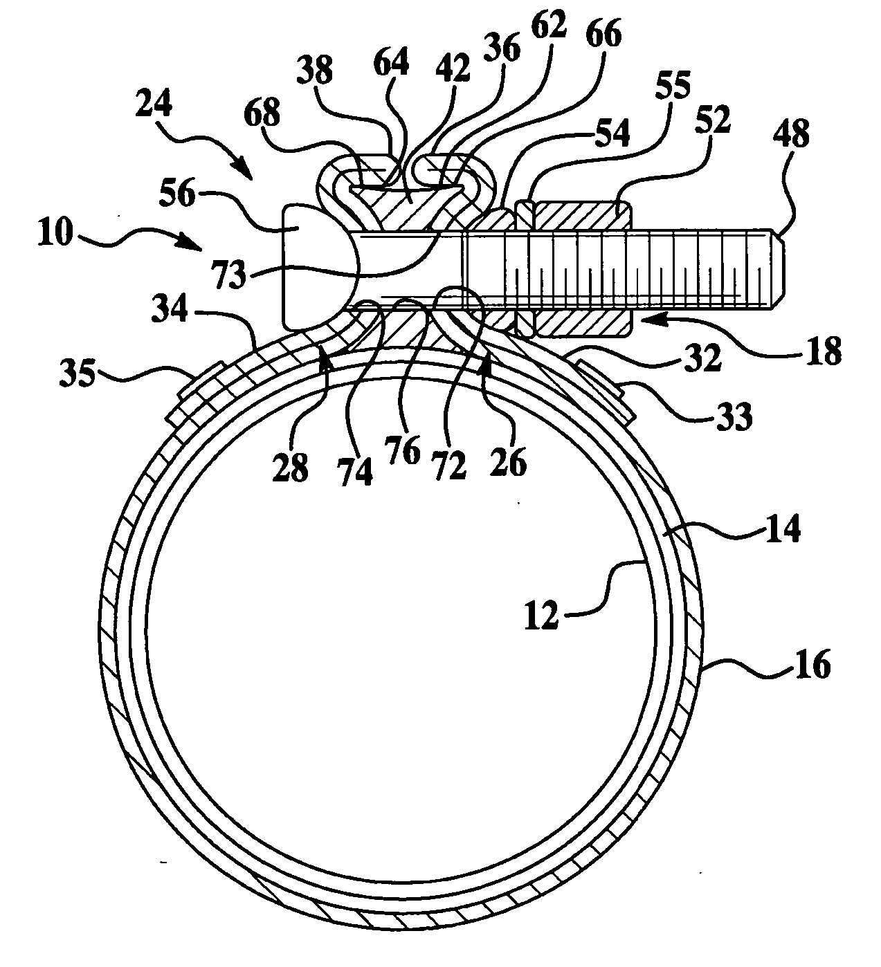
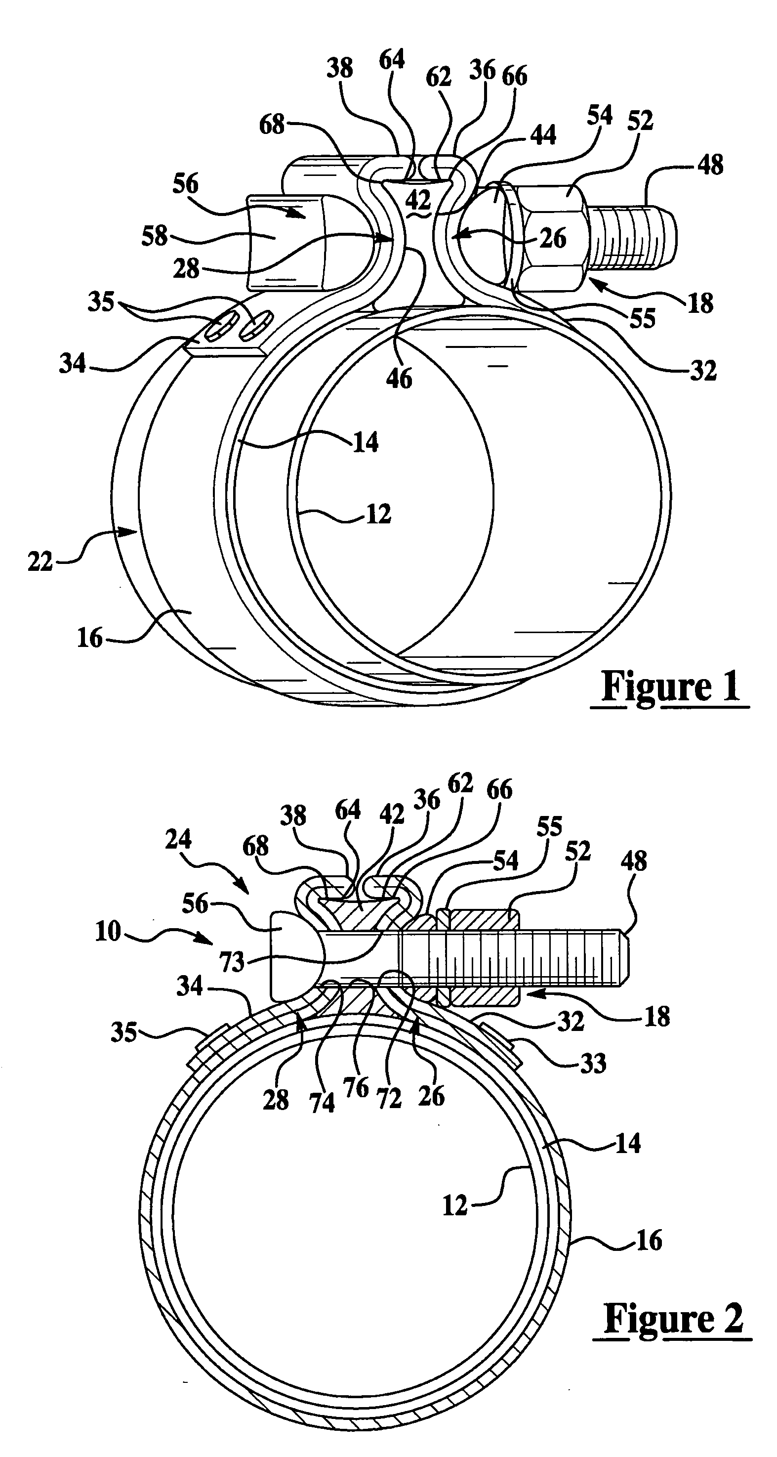
[0025] Referring now to the drawings, the invention is shown in two exemplary embodiments of a band clamp especially adapted for use in coupling pipe ends together to form a pipe joint in vehicle exhaust systems. In exhaust system applications, the band clamp is preferably made of steel. In the illustrated embodiments, the invention is implemented in a band clamp with a single bolt in the tightening mechanism in the manner shown in U.S. Pat. No. 4,629,226 to Cassel et al. The invention can also be implemented with a tightening mechanism having two bolts as disclosed in U.S. Pat. No. 4,813,270 to Cassel or U.S. Pat. No. 6,758,501 to Amedure et al. It will be appreciated as the description proceeds, that the invention is useful in many different applications and may be implemented in many other embodiments. For example, the invention can be used not only for band clamps that permit connecting pipes in a telescopic overlap condition, but also for pipe couplers that are typically applie...


PUM


Abstract

A band clamp having a band and a nut and bolt fastener. The band includes radially-extending opposed flanges each having an aperture for receiving the bolt. The bolt has a shank that includes a neck, a threaded body for receiving the nut, and a tapered transition from the neck to the threaded body. In one embodiment, the tapered transition extends only partially around the shank such that a portion of the neck has a common surface with the body. During tightening, the radially inward facing surface of the aperture in the flange can engage the threaded body and slide along the threaded body across the common surface and onto the neck without having to traverse and ride up over the tapered transition. In another embodiment, the nut has an angled shoulder that engages the tapered transition when the nut is tightened to the desired axial position on the bolt.

Description

CROSS-REFERENCE TO RELATED APPLICATION [0001] This application claims the priority of U.S. Provisional Application No. 60 / 629,569, filed Nov. 19, 2004, the entire contents of which are hereby incorporated by reference.FIELD OF THE INVENTION [0002] This invention generally relates to pipe clamps such as band clamps, pipe couplers and the like. BACKGROUND OF THE INVENTION [0003] Band clamps are commonly used for connecting pipes, hoses, and other tubular members together, such as exhaust pipes of an automotive exhaust system. Such connections are typically constructed in a telescopic overlap joint or in an end-to-end butt joint of two tubular members. To be effective, the connection between the tubular members should provide a suitable fluid-tight seal to prevent leakage. The connection should also have a high degree of mechanical strength and be capable of easy disassembly. [0004] A conventional band clamp includes a band defined by a cylindrical body portion that circumscribes tubul...

Claims


Application Information

Patent Timeline
Patent Type & Authority Applications(United States)
IPC IPC(8): F16L33/00
CPCF16B35/048F16L21/065F16L33/04Y10T24/1455F01N13/1855Y10T24/1441Y10T24/1451F01N13/1805F16L33/00
Inventor IGNACZAK, BRIAN T.AMEDURE, MICHAEL E.
Owner BREEZE TORCA PRODS
Learn More