Robotic welding cell unit

a robotic welding and cell unit technology, applied in forging/pressing/hammering equipment, manufacturing tools, forging/hammering/pressing machines, etc., can solve the problems of large capital expenditures and cost prohibitive situations for assembling these welding units, and achieve convenient loading and unloading of portable units, easy installation into beds, and more freedom of movement

a robotic welding and cell unit technology, applied in forging/pressing/hammering equipment, manufacturing tools, forging/hammering/pressing machines, etc., can solve the problems of large capital expenditures and cost prohibitive situations for assembling these welding units, and achieve convenient loading and unloading of portable units, easy installation into beds, and more freedom of movement

US20060108342A1Inactive Publication Date: 2006-05-25LINCOLN GLOBAL INC

Image

  • Robotic welding cell unit
  • Robotic welding cell unit
  • Robotic welding cell unit

Examples


Embodiment Construction

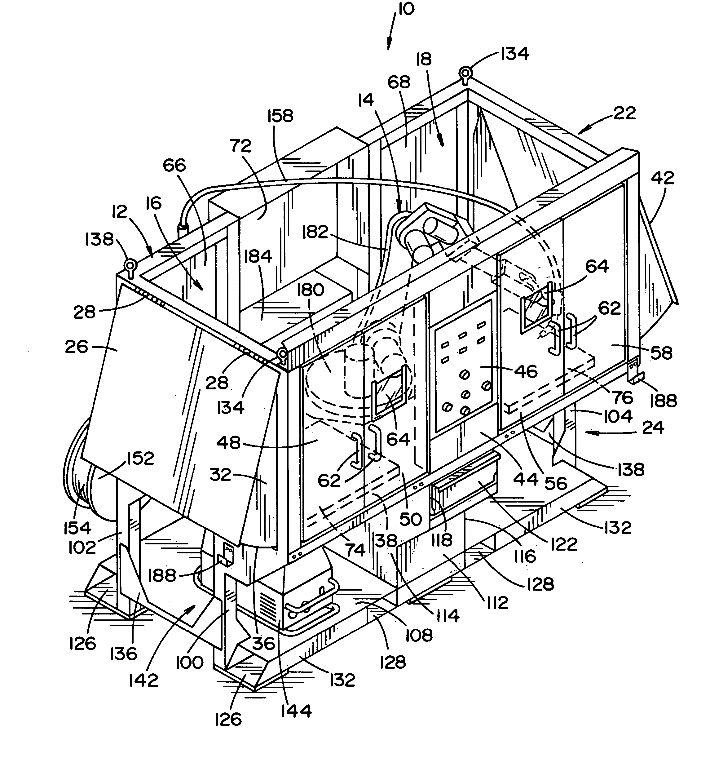
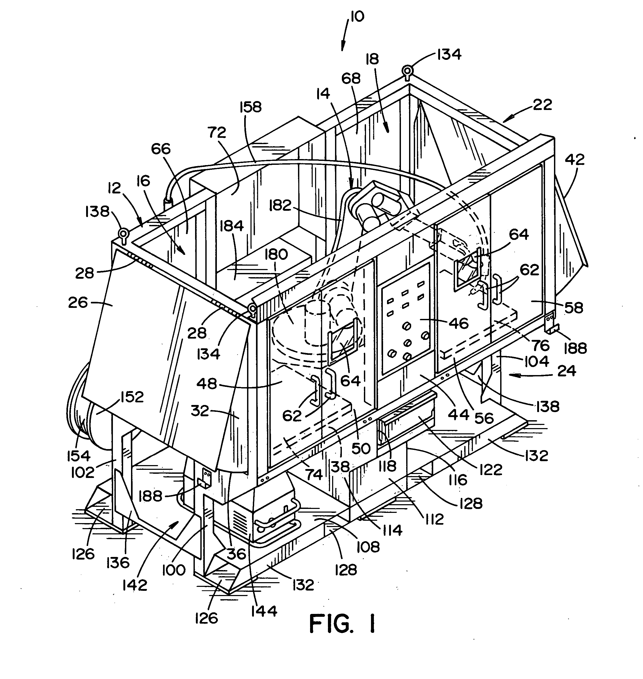
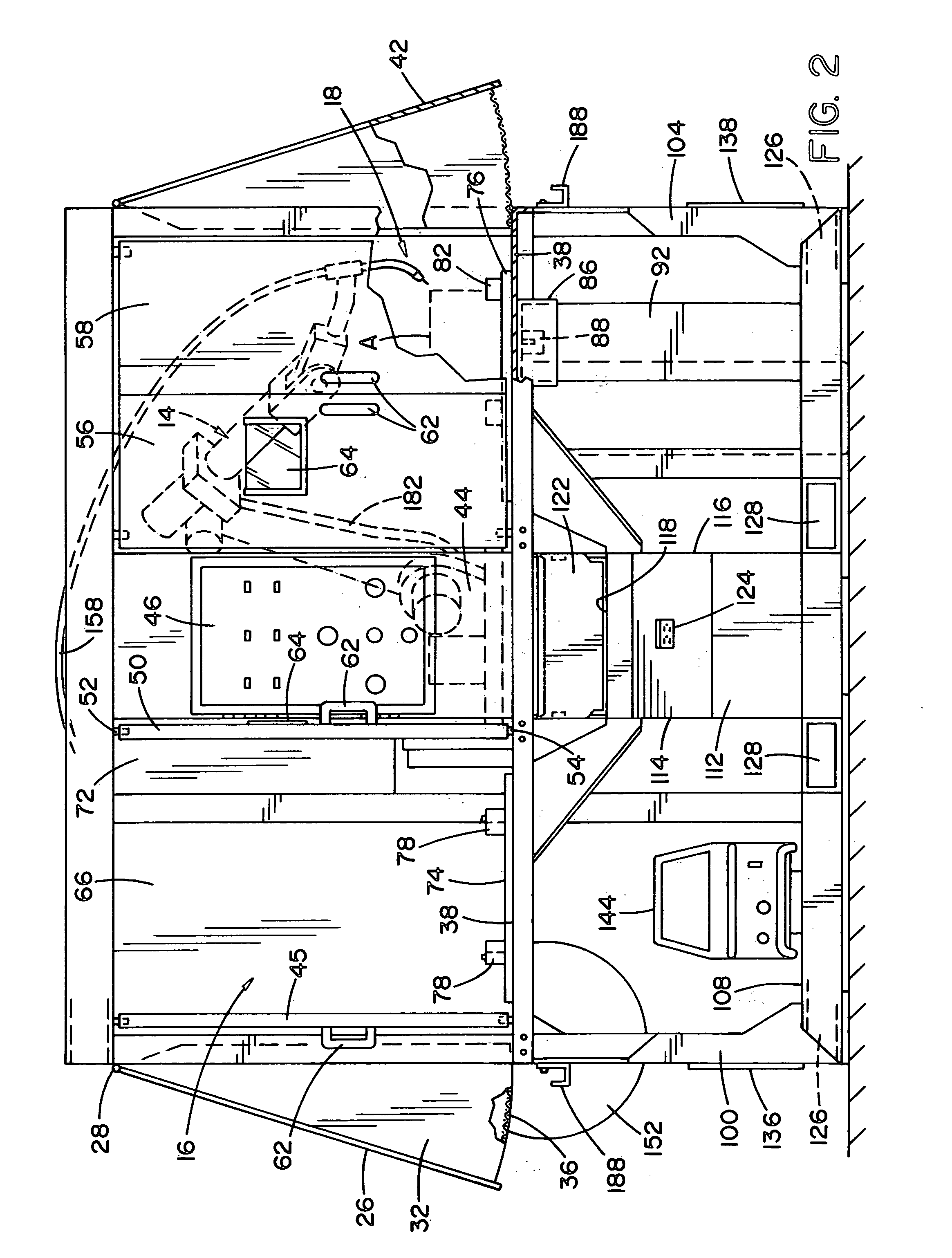
[0022] A portable welding cell unit 10 generally includes a frame 12, a robot 14 disposed within the frame, first and second welding stations 16 and 18 disposed within the frame and other components that will be described in more detail below. The frame 12 can generally be described as including an upper frame portion 22, which is enclosed with the exception of the top, to define the first and second welding stations 16, 18, and an open lower frame portion 24, which supports the upper frame portion. Both the upper frame portion 22 and the lower frame portion 24 have a generally rectangular parallelopiped configuration.

[0023] With reference to FIG. 1, the sides and bottom of the upper frame surround the welding stations 16 and 18. The side walls of the cell unit 10 can move to allow for more freedom of movement for the robot 14 inside the cell unit. In the depicted embodiment, a first upper side wall 26 attaches to the upper frame portion 22 of the cell unit via hinges 28 located at...


PUM

PropertyMeasurementUnit
clearance areaaaaaaaaaaa
freedom of movementaaaaaaaaaa
physical formaaaaaaaaaa

Abstract

A portable welding cell unit includes a frame structure in which first and second welding stations are disposed. A robot arm is also provided within the frame. The robot arm can pivot between the first and second welding stations such that a work piece can be welded in the first welding station while a work piece is being loaded into or unloaded from the second welding station.

Description

BACKGROUND OF THE INVENTION [0001] Robots have been used in welding operations for some time. An example of such is disclosed in U.S. Pat. No. 6,772,932, which is incorporated by reference. Typically, a robot arm having a welding torch at a distal end welds a work piece positioned on a work table. The work table is located in a welding cell and the robot is programmed to weld along a desired path. [0002] To increase the efficiency of these robot welding units, often times two work tables or robotic cells are provided. As the welding operation takes place in a first cell, in a second cell the completed work piece is being removed from the table and a new work piece is being placed onto the table. Upon completion of the weld in the first cell, the robot moves to the second cell having the newly placed work piece positioned on the work table and begins welding the newly placed work piece in the second cell. [0003] These dual cell Welding units are typically assembled on site. Large cap...

Claims


Application Information

Patent Timeline
25 May 2006
Publication
US20060108342A1
IPC
B23K9/12
CPC
B23K9/323
Inventors
SAMODELL, RALPH M.; FARAH, SAMIR F.