
Space mechanical arm suspension microgravity simulation device

A space manipulator and microgravity simulation technology, applied in the field of simulation experiments, can solve problems such as the degree of freedom of the manipulator, range limitation, torque deviation at joints, and the influence of spacecraft attitude, achieving difficult control, high motion accuracy, and improved Follow the effects of dynamic features in real time

Pending Publication Date: 2021-02-26
TIANJIN AEROSPACE ELECTROMECHANICAL EQUIP RES INST
View PDF0 Cites 8 Cited by
  • Summary
  • Abstract
  • Description
  • Claims
  • Application Information

AI Technical Summary

Problems solved by technology

During the test, the degree of freedom and range of the manipulator's movement are greatly limited
Moreover, since there is no need to consider the influence of the force and moment of the mechanical arm on the fixed installation, gravity unloading is mostly carried out for the main arm of the mechanical arm. The overall use of double or single lifting points, although the overall gravity of the mechanical There is a large deviation in the torque at
[0005] When carrying out tests such as target acquisition with a robotic arm of a spacecraft, the robotic arm is installed on an air bearing platform or a parallel mechanism with six degrees of freedom, and the torque deviation at the root of the robotic arm will have a great impact on the attitude of the spacecraft. , making the capture simulation test fail
Sometimes the movement of the robotic arm is restricted for more realistic simulations to verify the state of the spacecraft in experiments such as capture

Method used


Image

  • Space mechanical arm suspension microgravity simulation device
  • Space mechanical arm suspension microgravity simulation device
  • Space mechanical arm suspension microgravity simulation device

Examples


Embodiment Construction

[0052] It should be noted that, in the case of no conflict, the embodiments of the present invention and the features in the embodiments can be combined with each other.

[0053] In describing the present invention, it should be understood that the terms "center", "longitudinal", "transverse", "upper", "lower", "front", "rear", "left", "right", " The orientations or positional relationships indicated by "vertical", "horizontal", "top", "bottom", "inner", "outer", etc. are relative orientations or positional relationships, which are only for the convenience of describing the present invention and simplifying the description, and It is not to indicate or imply that the device or element referred to must have a particular orientation, be constructed in a particular orientation, or operate in a particular orientation, and thus should not be construed as limiting the invention. In addition, the terms "first", "second", etc. are used for descriptive purposes only, and should not be ...


PUM


Abstract

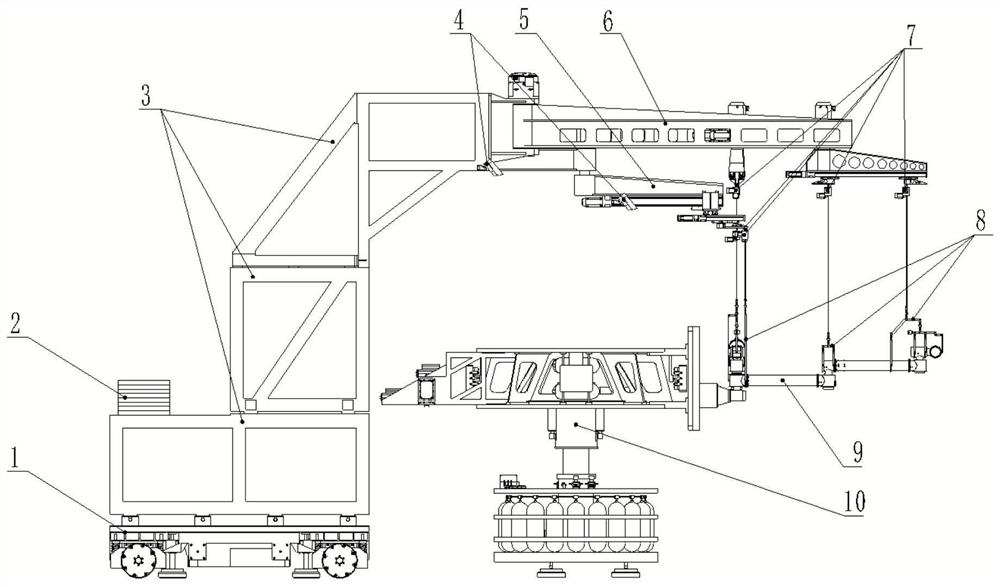
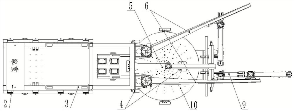
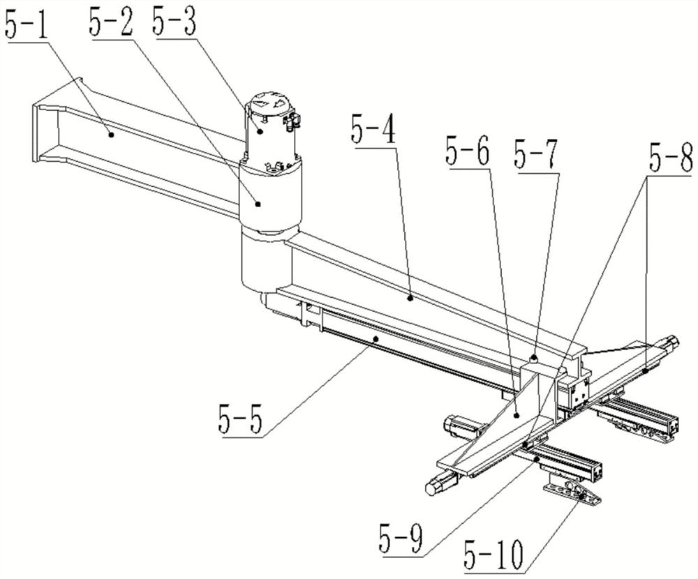
The invention provides a space mechanical arm suspension microgravity simulation device, which belongs to the field of simulation experiments, and comprises a mechanical swing arm mounting platform, asix-degree-of-freedom table and a camera, a target point on the six-degree-of-freedom table is measured in real time to obtain the position and attitude change of the six-degree-of-freedom table, andthe mechanical swing arm mounting platform is controlled to move along with the six-degree-of-of-freedom table; the mechanical swing arm mounting platform comprises an omni-directional moving platform, a balance weight and a mechanical swing arm bracket; the omni-directional moving platform moves omni-directionally in a plane; a counterweight, which is used for balancing the whole centroid of theomni-directional mobile platform, and a mechanical swing arm, the motion of the mechanical swing arm bracket is used for compensating the motion precision of the full-moving platform. The action of the gravity of the mechanical arm on the posture of the spacecraft when the mechanical arm is unfolded is eliminated, meanwhile, more motion freedom degrees and motion ranges of the mechanical arm arereserved, and the unfolding range of the space mechanical arm is adapted to in a large range.

Description

technical field [0001] The invention belongs to the field of simulation experiments and relates to a space manipulator suspension microgravity simulation device. Background technique [0002] It is a commonly used method in the field of aerospace to simulate and simulate the special working environment of the spacecraft to carry out test experiments to verify the structural performance of the spacecraft on the ground, and it is also a strategy that takes into account both economy and timeliness in the development process. [0003] In recent years, space manipulators or space robots have taken on more and more important tasks in space exploration and development, and can replace astronauts in the harsh space environment to complete various tasks such as target capture, fault maintenance, garbage cleaning, and star surface sampling. Task. The space manipulators developed based on the low-gravity environment and application background in space mostly have the characteristics o...

Claims


Application Information

Patent Timeline
Patent Type & Authority Applications(China)
IPC IPC(8): B64G7/00
CPCB64G7/00
Inventor 齐放吴跃民李博朱朝晖
Owner TIANJIN AEROSPACE ELECTROMECHANICAL EQUIP RES INST
Learn More