Thin hybrid magnetization type ring magnet, yoke-equipped thin hybrid magnetization type ring magnet, and brush-less motor

a hybrid magnetization and hybrid magnet technology, applied in the direction of magnetic circuit rotating parts, magnetic bodies, magnetic circuit shapes/forms/construction, etc., can solve the problems of large cogging torque, inferior surface magnetic flux, and inability to fit inside the magnet, so as to improve the performance, reduce the cogging torque of the brushless motor, and increase the torque per unit volume of the magnet

Active Publication Date: 2006-06-01
AICHI STEEL
View PDF7 Cites 69 Cited by
  • Summary
  • Abstract
  • Description
  • Claims
  • Application Information

AI Technical Summary

Benefits of technology

[0042] Due to this structure, it is possible by using a thin hybrid magnetized ring magnet to simultaneously achieve both a decrease in the cogging torque of the brushless motor and an increase in torque per unit volume of magnet. It is therefore possible to design for an increase in performance and a decrease in size of the motor. And in the case of an outer rotor-type motor, by using a soft magnetic body in the rotor yoke, same as the method described above for the inner rotor-type motor, it is possible to lengthen the distance between magnetic poles (permeance will increase), and therefore it is possible to further improve the surface magnetic flux of the magnetic poles.

Problems solved by technology

In comparison to polar anisotropically magnetized ring magnets, the alignment and magnetization of radially magnetized ring magnets is good, but surface magnetic flux is quite inferior, and because the magnetic flux changes abruptly at the interface between the magnetic poles there is a large amount of cogging torque, which needed to be improved.
Therefore, even if the wall thickness of the bonded magnet is made ½ the width of one magnetic pole, because sufficient magnetic flux for realizing alignment is distributed along the surface part of the ring-shaped bonded magnet, the inside part of the magnet is not aligned, and the wall thickness is not effectively utilized.
That is, there is the problem of an increase in the amount of magnet material necessary for a motor which will generate the same torque.

Method used


Image

  • Thin hybrid magnetization type ring magnet, yoke-equipped thin hybrid magnetization type ring magnet, and brush-less motor
  • Thin hybrid magnetization type ring magnet, yoke-equipped thin hybrid magnetization type ring magnet, and brush-less motor
  • Thin hybrid magnetization type ring magnet, yoke-equipped thin hybrid magnetization type ring magnet, and brush-less motor

Examples


Embodiment Construction

[0062] The present invention is explained below through the use of embodiments. However, the present invention is not limited to the embodiments stated hereafter.

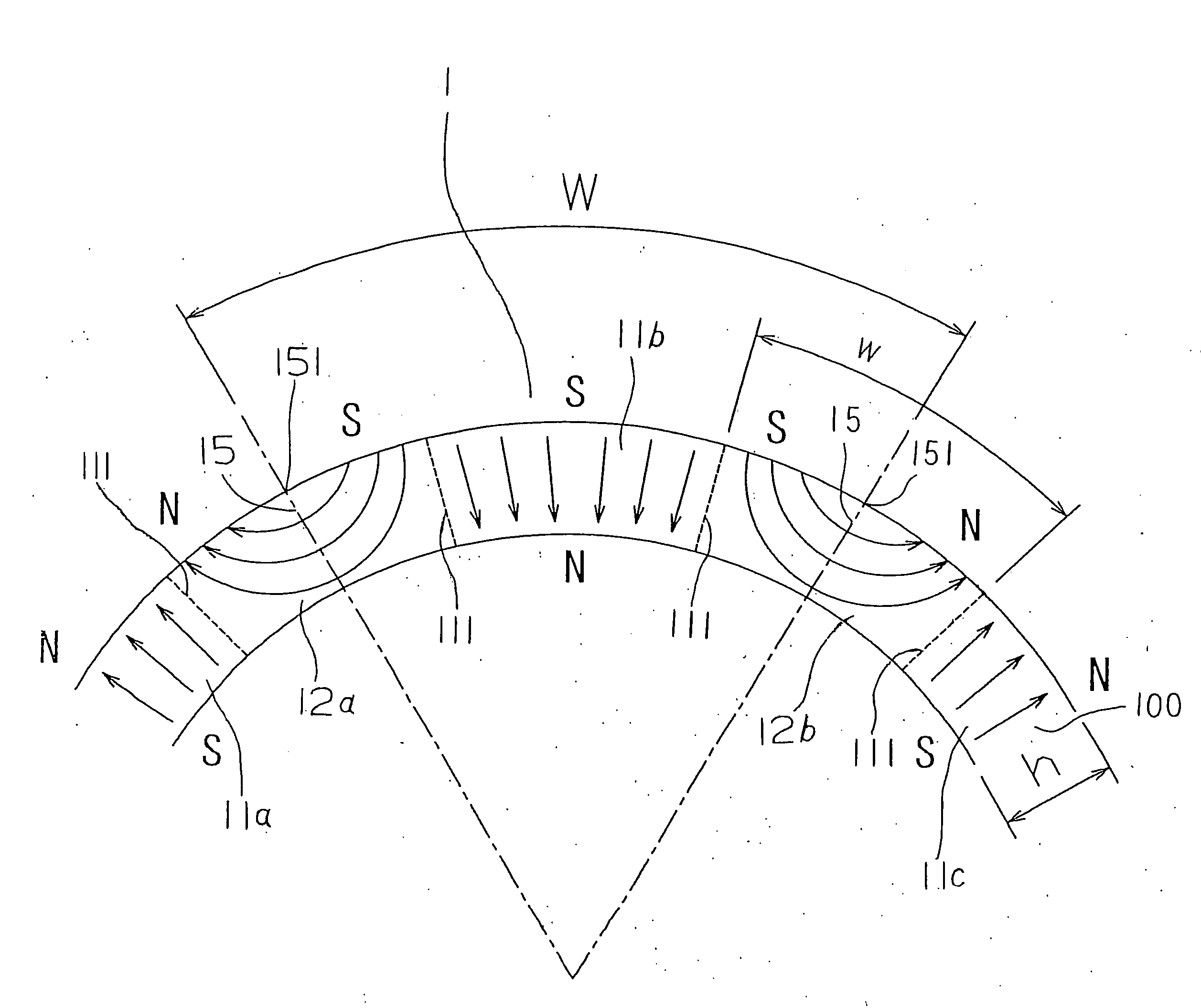
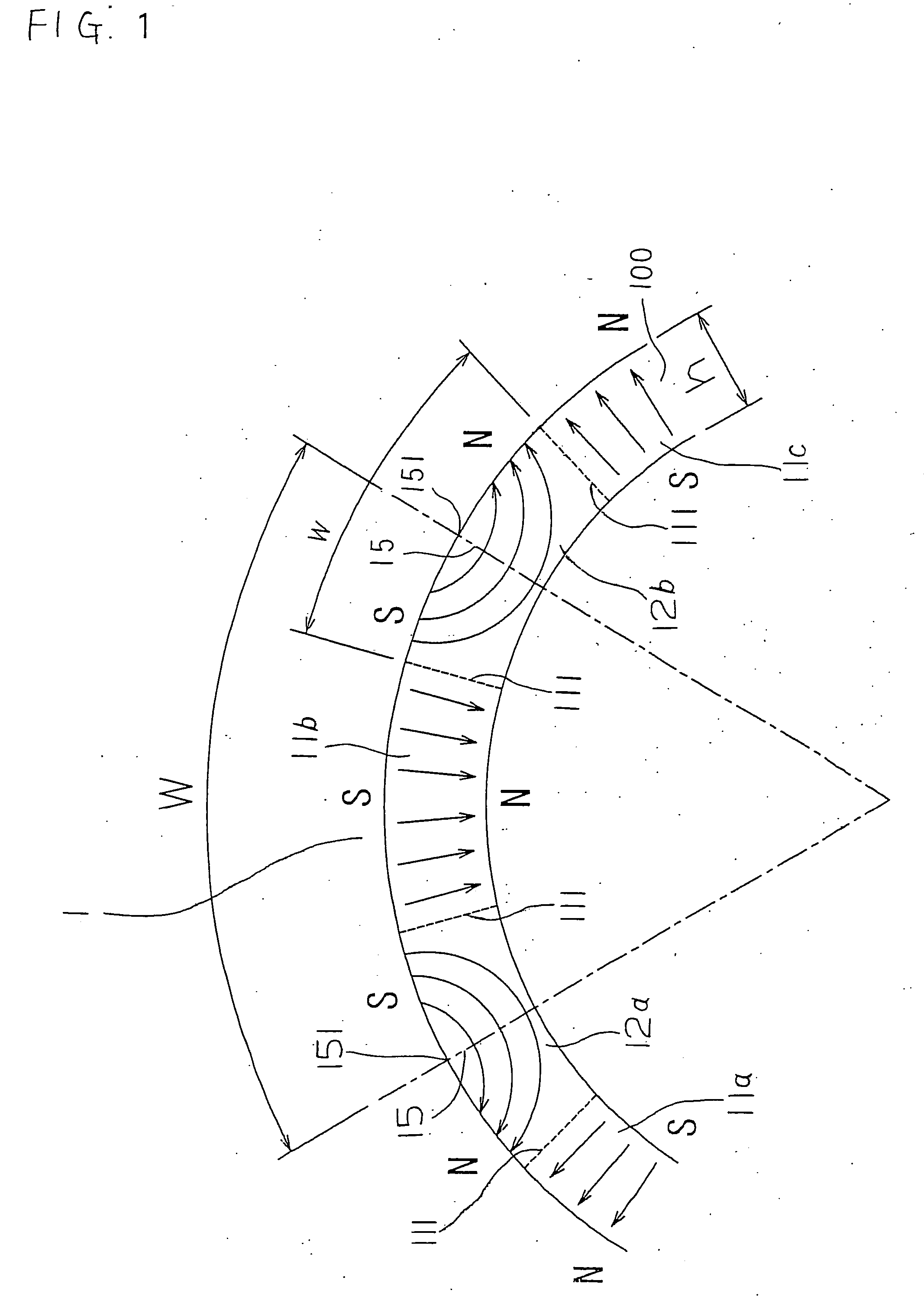
[0063] The hybrid magnet structure having to do with a specific embodiment of the present invention is shown in. FIG. 1. Hybrid magnet 1 has a ring shape centered around the axis. FIG. 1 shows a magnetic pole and its vicinity in a cross sectional diagram perpendicular to the axis of hybrid magnet 1 of the embodiment. By way of example, Nd—Fe—B anisotropic rare earth bonded magnet 100 is used in hybrid magnet 1.

[0064] The arrows within hybrid magnet 1 indicate the magnetization pattern of the magnet interior.

[0065] Because the present embodiment is an anisotropic bonded magnet, magnetic field alignment is performed before magnetization, and the alignment pattern is the same as in FIG. 1. Hybrid magnet 1 of the present embodiment has 10 magnetic poles. The magnetization pattern was described above and is therefore omitted ...


PUM

PropertyMeasurementUnit
thicknessaaaaaaaaaa
diameteraaaaaaaaaa
widthaaaaaaaaaa

Abstract

The present invention provides miniaturization of brushless motors and brush motors used in electric devices, a ring magnet which simultaneously achieves both high torque and a reduction in cogging torque, a ring magnet with yoke, and a brushless motor. The thin hybrid magnetized ring magnet of the present invention is structured of, in a ring magnet comprised of a plurality of magnetic poles, a radially magnetized main pole and an interface for which the interface of the adjoining main pole is polar anisotropic. When the thin hybrid magnetized ring magnet structured in this manner is applied to a brushless motor, in the case of radial magnetizing, the abrupt change in magnetic flux of the interface between the magnetic poles becomes smooth and cogging torque is greatly reduced due to polar anisotropic magnetization of the interface. At the same time, by polar anisotropically magnetizing the interface between the magnetic poles, magnetic flux is concentrated on the radially magnetized main pole, and in comparison to only radial magnetization, maximum surface magnetic flux improves and it is possible to attain high torque.

Description

BACKGROUND OF THE INVENTION [0001] 1. Field of the Invention [0002] The present invention relates to a magnet used in a brushless motor used in electronic devices, a brush motor rotor or stator; a magnet with yoke; and a motor in which they are used. [0003] 2. Description of the Related Art [0004] (Patent Reference 1) Japanese Unexamined Patent Application (Kokai) 6-124822 [0005] The need for smaller, high performance motors has been increasing in recent years. Small and high-performance brushless motors with high torque as well as low cogging torque are also needed. [0006] Ring magnets used in brushless motors are ordinarily used having been magnetized with a plurality of poles. With respect to alignment and method of magnetization of those magnets, there are radially magnetized ring magnets and polar anisotropically magnetized ring magnets. [0007] In comparison to polar anisotropically magnetized ring magnets, the alignment and magnetization of radially magnetized ring magnets is ...

Claims


Application Information

Patent Timeline
Patent Type & Authority Applications(United States)
IPC IPC(8): H02K21/12H02K1/27H01F7/02H01F13/00H01F41/02H02K29/03
CPCH01F13/003H01F41/028H02K1/2733H02K29/03H01F7/0273
Inventor HONKURA, YOSHINOBUMATSUOKA, HIROSHINAGAYA, DAISUKE
Owner AICHI STEEL
Why Eureka
Try Eureka