Tunable frequency selective surface

a frequency selective surface and frequency selective technology, applied in the direction of antenna details, electrically short antennas, antennas, etc., can solve the problems of not being able to achieve rapid tuning, many of the above methods are not practical, and the effect of reducing the usefulness of continuous tunable surfaces

Active Publication Date: 2006-06-01
HRL LAB
View PDF13 Cites 76 Cited by
  • Summary
  • Abstract
  • Description
  • Claims
  • Application Information

AI Technical Summary

Problems solved by technology

Although the above-mentioned methods are used to tune the FSS, these methods are not ideal for use with a tunable antenna.
Many of the above methods are not practical for rapid tuning because they use moving metal parts, or pumping dielectric liquids.
Some of them include switching between discrete states using transistors, which is less useful than a continuous tunable surface.
Others require bulk ferrite, ferroelectric, or electrooptic materials, which can be lossy and expensive.
None of the prior art achieves the capabilities of the present technology, even though a need exists for those capabilities.

Method used


Image

  • Tunable frequency selective surface
  • Tunable frequency selective surface
  • Tunable frequency selective surface

Examples


Embodiment Construction

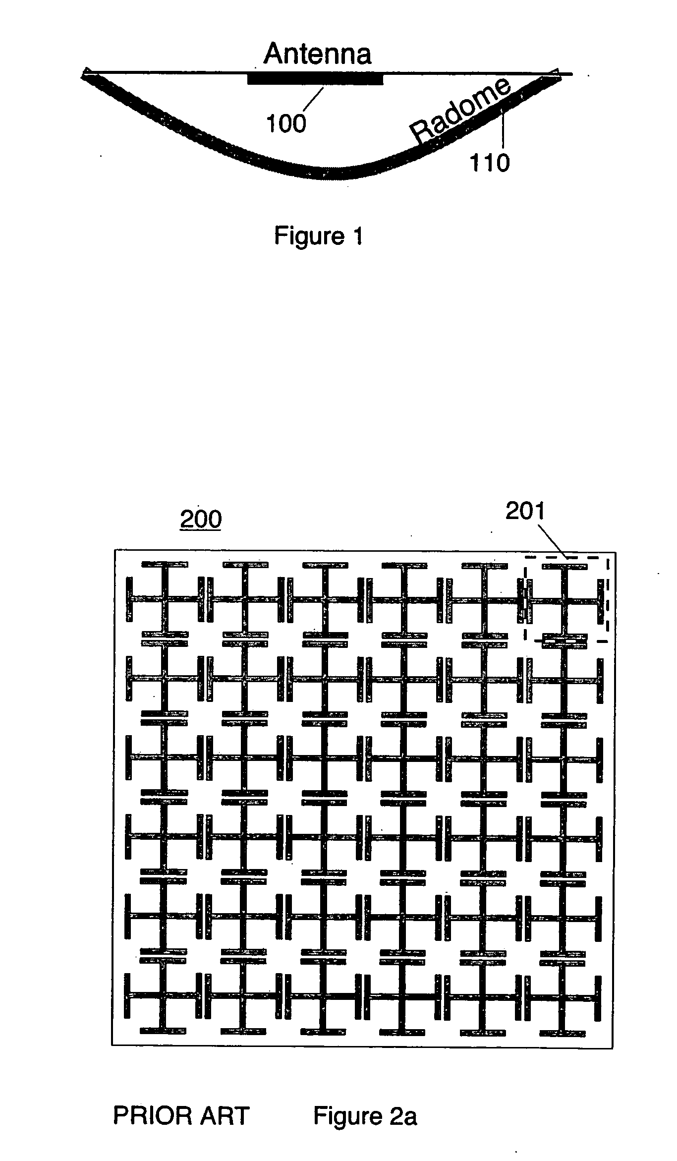
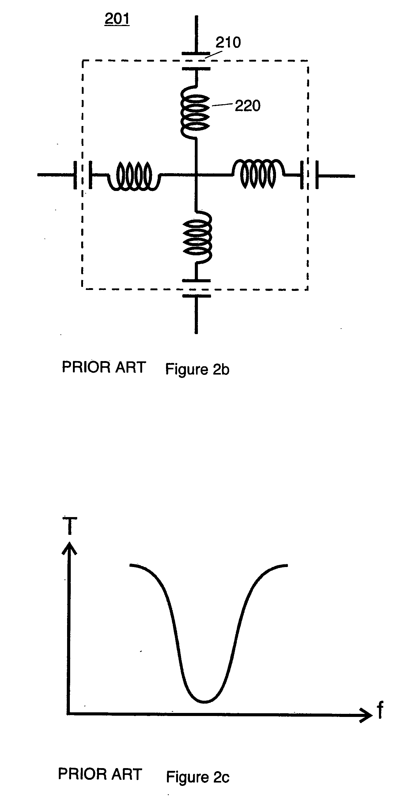
[0064] Of the two surfaces that are commonly used in FSS design, the Inverse structure 300 is the most appropriate in designing a TFSS. The series LC circuit 510, shown in FIG. 5a, used by the Jerusalem cross 200 is difficult to use because it lacks a continuous metal path throughout the surface, so it is difficult to provide DC bias to the internal cells. Whereas, the parallel LC circuit 511, shown in FIG. 5b, used by Inverse structure 300, does not have this limitation.

[0065] The parallel circuit 512, which is an equivalent circuit for LC circuit 511, can be constructed as a varactor diode 530 in parallel with a narrow metal wire 540, which acts as an inductor, and in parallel with a DC blocking capacitor 550, as shown in FIG. 5c.

[0066] The parallel circuit 513, which is another equivalent circuit for LC circuit 511, can also be constructed as two varactor diodes 560 and 561 in parallel with a narrow metal wire 570, which acts as an inductor, as shown in FIG. 5d.

[0067] Using va...


PUM


Abstract

An apparatus and methods for operating a frequency selective surface are disclosed. The apparatus can be tuned to an on / off state or transmit / reflect electromagnetic energy in any frequency. The methods disclosed teach how to tune the frequency selective surface to an on / off state or transmit / reflect electromagnetic energy in any frequency.

Description

FIELD OF THE INVENTION [0001] This technology relates to a frequency selective surface that can be tuned to an on-state, off-state and / or can transmit / reflect electromagnetic energy in any frequency band. BACKGROUND AND PRIOR ART [0002] Antennas 100 may be hidden behind a radome 110, see FIG. 1, particularly if they are being used in an application where they could be exposed to the environment. The radome protects the antenna from both the natural environment such as rain and snow, and the man-made environment such as jamming signals. Often, the radome is made so that it transmits electromagnetic energy within a narrow band centered around the operating frequency of the antenna, so as to deflect or reflect jamming signals at other frequencies. This is done using a frequency selective surface (FSS), having a grid or lattice of metal patterns or holes in a metal sheet. The design and construction of FSSs is well known to those skilled in the art of radome design and electromagnetic m...

Claims


Application Information

Patent Timeline
Patent Type & Authority Applications(United States)
IPC IPC(8): H01Q15/24
CPCH01Q15/24H01Q15/002
Inventor SIEVENPIPER, DANIEL F.
Owner HRL LAB
Why Eureka
Try Eureka