First, despite efforts to arrange tables, chairs and visual aids within large conference rooms in ways that foster communication between attendees, often the end result is a configuration that adversely affects communication.
Here, where all attendees face generally in one direction toward the display screen, attendees cannot easily make eye contact with, or observe other visual queues from, other attendees and hence cannot determine if concepts are being understood, if other attendees want to interject comments or agree or disagree with information presented.
Clearly lack of visual queues reduces communication effectiveness appreciably.
When chairs are rotated away from a presenter or fields of view are diverted from the presenter, the presenter loses the ability to sense visual queues.
Second, while movement between large group, small team and individual activities and spaces that facilitate those activities is, in theory, supposed to be fluid, in reality, such movement is usually interrupted and disjointed.
In this regard, while people in large groups often become energized when common goals and tasks for achieving those goals are identified and when tasks are initially assigned to team members, after leaving a conference, attendees often lose focus, start to question the common goals or tasks assigned to achieve the goals and / or turn their attention to other activities unrelated to the common goals and tasks.
In short
momentum is lost when the large group breaks up to pursue assigned tasks.
Third, while electronic display screens are advantageous for sharing information among groups and teams of people, currently such displays are relatively expensive and are usually dedicated to single conference spaces.
For this reason, while large electronic displays may be provided in large conference spaces for use by large groups where the cost associated therewith is justifiable, in many cases such displays are not provided in smaller conference spaces.
Fourth, many people find it difficult to share their ideas and concepts in large groups and, in particular, in groups where other group members will likely have different and divergent ideas and where some group members may have relatively strong personalities.
Therefore, when goals, tasks and personal skills are discussed in large group conferences, often many people that have different and valuable views, suggestions and comments do not express themselves and goals and tasks are set without the benefit thereof and, in many cases, without complete acceptance by all group members.
While iterative large group and small team conferences may minimize the effects of this problem, in many cases the lack of fluidity between large and small groups and associated spaces causes conference attendees to forgo such solutions and instead the group ploughs ahead without the benefit of all ideas being expressed and without complete buy in to group goals.
Fifth, providing many different spaces that are each dedicated to one type of use (e.g., large conferencing, small team conferencing or individual private use) is relatively expensive and often results in spaces that are relatively underutilized.
For instance, in many cases, while a company may periodically need a large conference space to share information, in many cases such large conference spaces will go unused during more than 90% of normal
business hours.
Sixth, requiring people to separate and come together multiple times and to break the flow of activities between different spaces breaks trains of thought and generally slows
momentum toward achieving goals.
Where goals are slowly achieved businesses often fail.
Unfortunately, while multi-table assemblies deal with some of the problems discussed above, such assemblies do not address other problems.
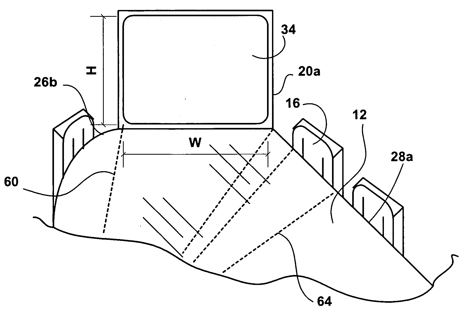
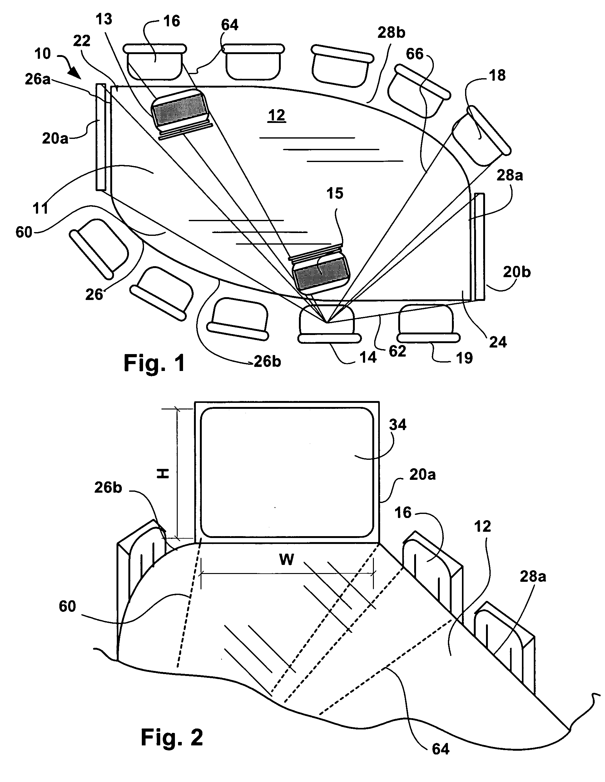
For instance, multiple table assemblies do not address the issues related to location of large display screens or other visual aids that require conference attendees to physically turn away from other attendees at a conference in order to view presented information or the fact that attendees that use the visual aids are located in commanding positions that reduce criticism and comments from other attendees.
As another instance, multiple table assemblies do not address issues related to providing electronic displays for each of a plurality of smaller conference table configurations when breakout sessions occur.
Indeed, where only a single electronic display is provided in a large conference space, when breakout sessions occur, the single display can only be used by members of one of the breakout sessions at a time.
As still one other instance, while separate table assemblies can be moved to different locations within a large conference space to facilitate breakout sessions, such physical distance between tables without visual barriers of any type (e.g., vertical walls of partition systems of some type) often is insufficient to give people the feeling of being in a space that is confidential or at least semi-confidential with respect to the other areas of the larger space.
As in the case of sharing ideas in large groups, many people have difficulty sharing ideas in spaces where
confidentiality is suspect.
In addition, even where separate table assemblies are provided to facilitate both large conferences and small breakout sessions, it is believed that several factors discourage using the tables separately to facilitate multiple breakout sessions.
First, the lack of relatively expensive electronic display screens for use with each separate table
assembly discourage breakout sessions using the separate tables.
Second, problems associated with suspect
confidentiality have discouraged separation of the table assemblies to facilitate break out sessions.
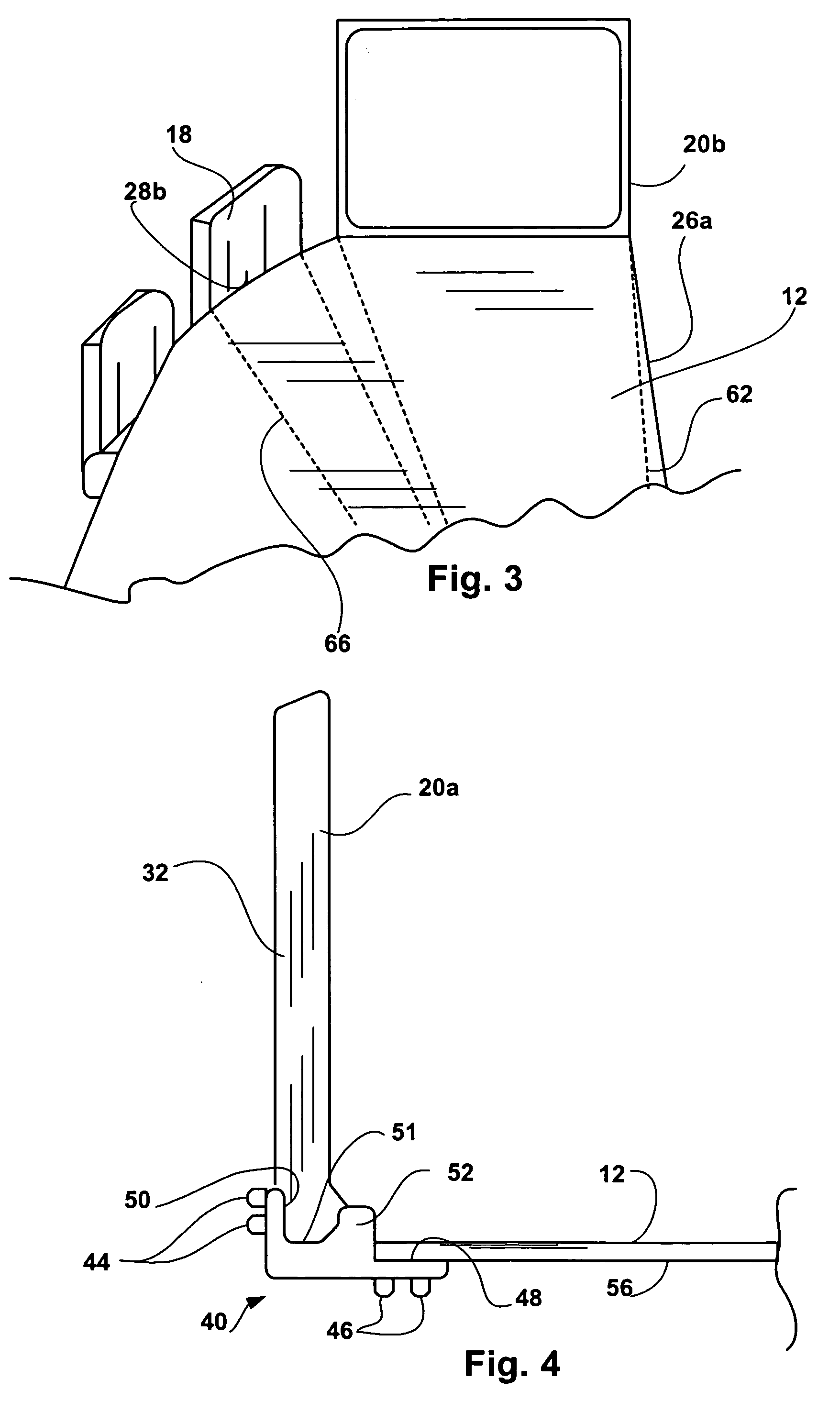
Third, it is believed that any work required to rearrange tables about a
conference room including disconnecting linking mechanisms between tables, unlocking
caster brake mechanisms, etc., operates as a strong impediment to rearranging those tables.
The impediment is still further exacerbated where the locking and unlocking and
brake mechanisms are not completely intuitive to users as many users will not routinely use such features or where the activities require users to crawl under table tops to perform the locking and linking activities.
Thus, despite added costs associated with providing a versatile table configuration, the table configuration is not used for its intended purpose.
One problem with sharing conference information via laptops is that attendees focus on the information on their laptops instead of making
visual contact with the other attendees.
Where presentation information is provided via laptops, non-presenting attendees cannot use their laptops for other purposes.

