
Insulating concrete block

a technology of concrete blocks and blocks, applied in the field of insulation concrete blocks, can solve problems such as problems that are encountered

Active Publication Date: 2006-06-08
BUILDBLOCK BUILDING SYST
View PDF62 Cites 19 Cited by
  • Summary
  • Abstract
  • Description
  • Claims
  • Application Information

AI Technical Summary

Problems solved by technology

While many of the insulating concrete form systems have met with success, problems are nevertheless encountered while fitting the blocks together, pouring the concrete into the blocks, and applying finishing materials to the formed wall.

Method used


Image

  • Insulating concrete block
  • Insulating concrete block
  • Insulating concrete block

Examples


Embodiment Construction

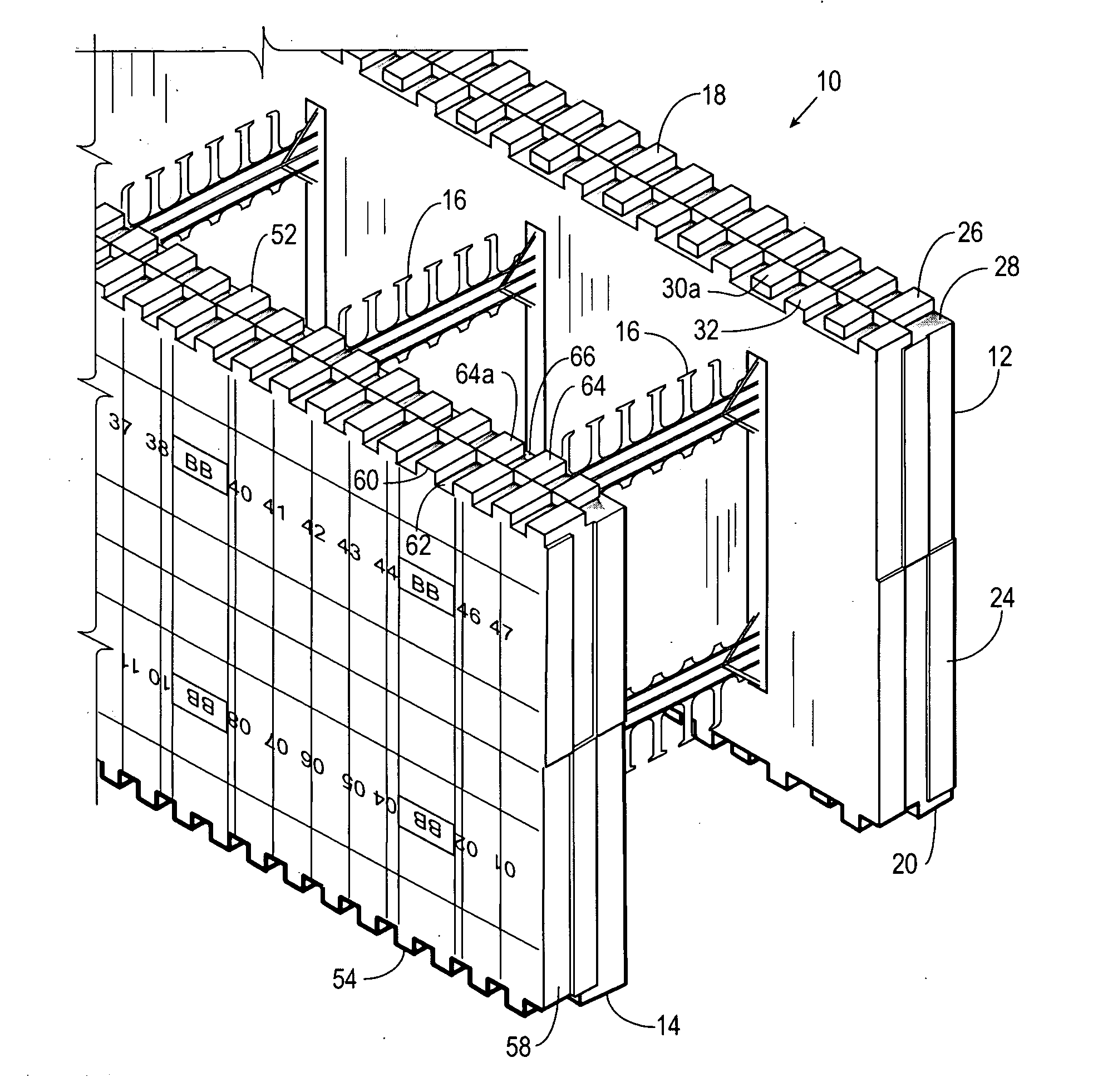
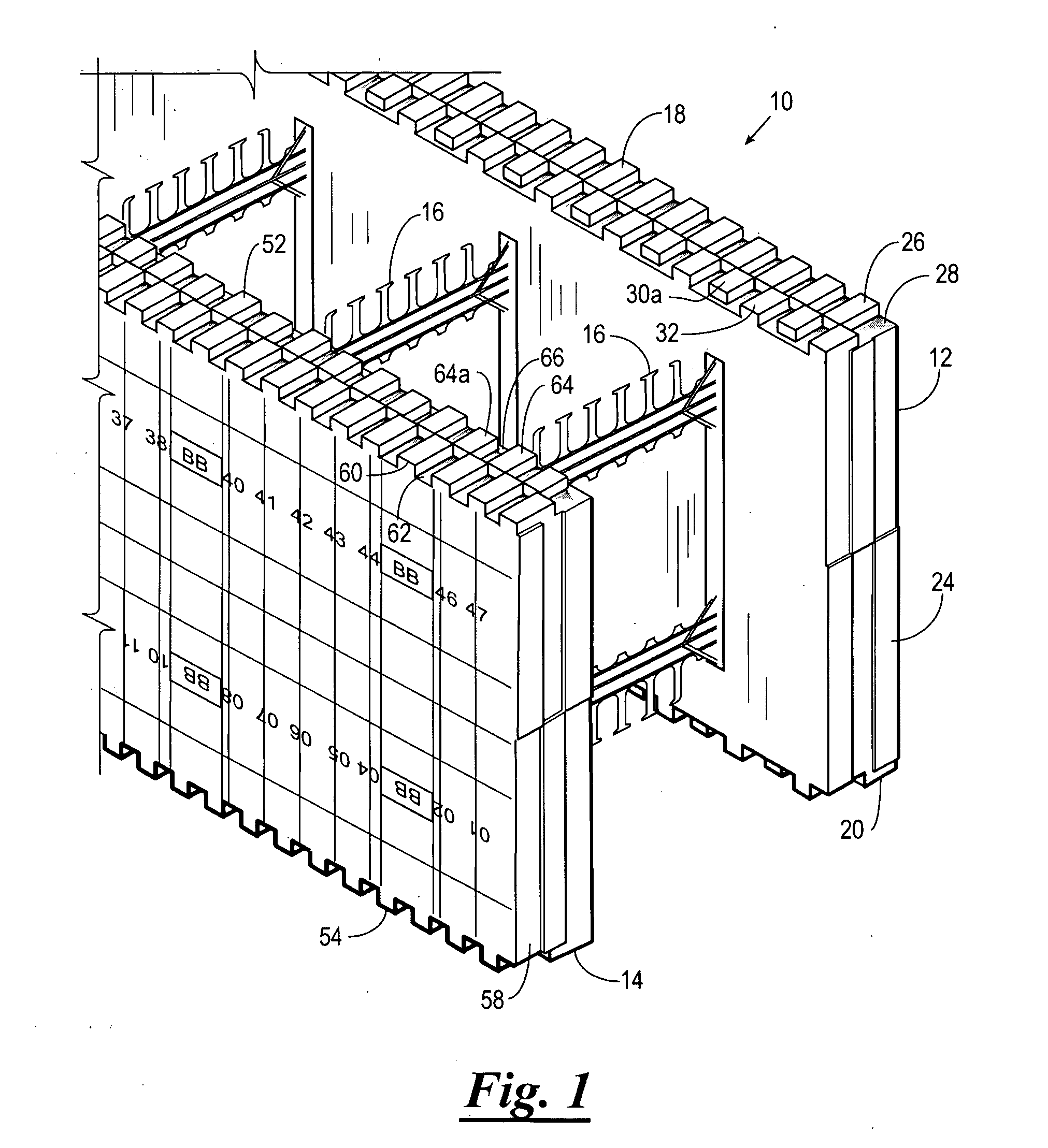
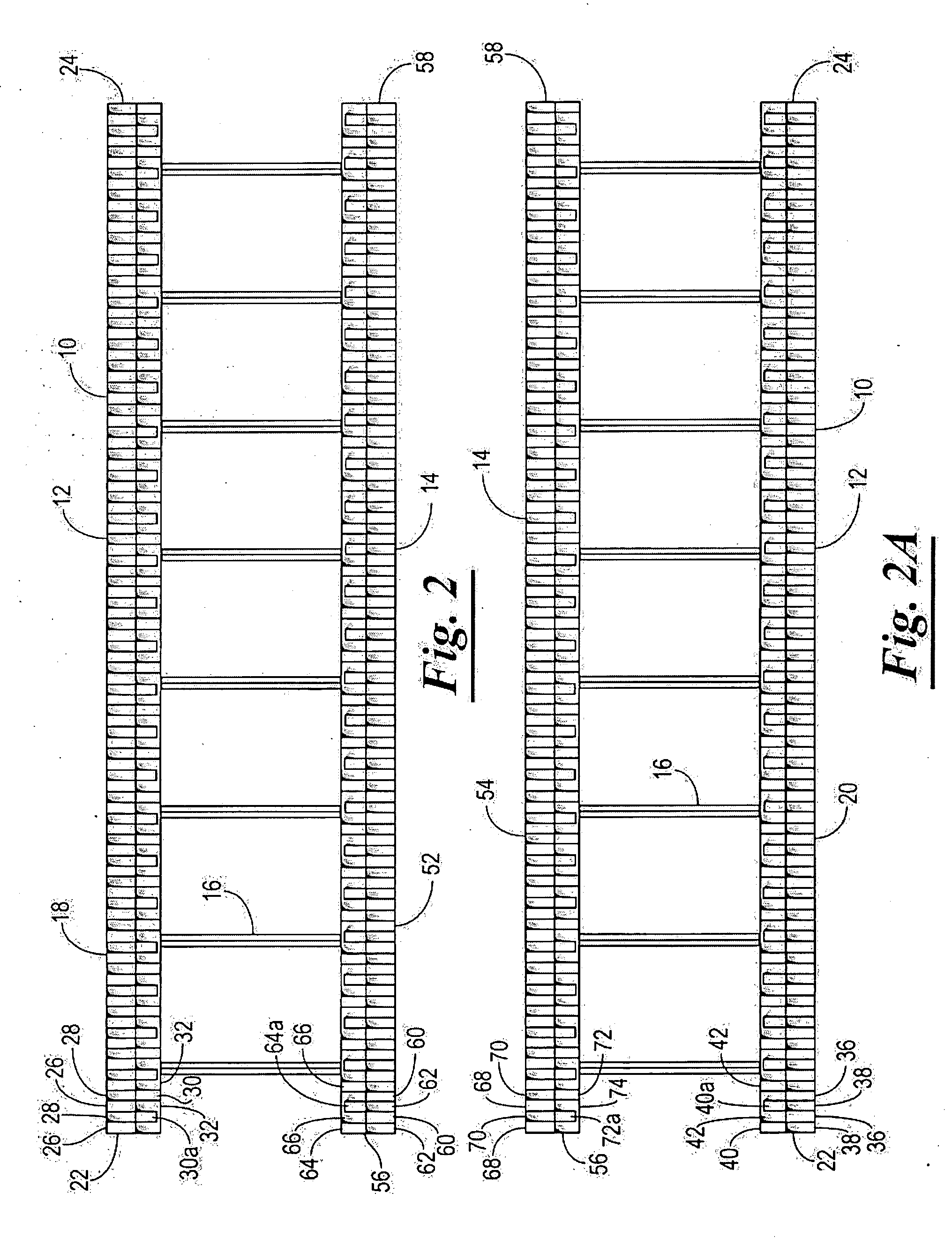
[0023] Referring now to the drawings, and more particularly to FIGS. 1-4, an insulating concrete block 10 (referred to hereinafter as “block 10”) constructed in accordance with the present invention is illustrated. The block 10 is adapted to be interlocked with other insulating construction blocks to form an insulating concrete form for casting concrete. The block 10 is formed from two panels 12 and 14 interconnected to one another with a plurality of web structures 16.

[0024] The panel 12 has a top end 18 (FIG. 2), a bottom end 20 (FIG. 2A), a first end 22, and a second end 24. The top end 18 has an outside row of a plurality of projections 26 which are spaced apart to define a plurality of corresponding recesses 28 and an inside row of projections 30 and 30a which are spaced apart to define a plurality of recesses 32. The projections 30 and 30a of the inside row are different in size to one another and are alternated relative to one another. Moreover, the projections 30 and 30a of...


PUM


Abstract

An insulating concrete block adapted to be interlocked with other insulating concrete blocks to form an insulating concrete form for casting concrete. The insulating concrete block including a first foam panel and a second foam panel supported in a spaced apart, parallel relationship to form a concrete receiving cavity. Each of the first panel and the second panel having a top end, a bottom end, a first end, and a second end. The top end and the bottom end of each of the first and second panels having an outside row of a plurality of projections and an inside row of a plurality of projections. The projections of the outside row being spaced apart to define a plurality of recesses and the projections of the inside row being spaced apart to define a plurality of recesses with the projections of the outside row being adjacent to the recesses of the inside row and the recesses of the outside row being adjacent projections of the inside row. At least some of the projections of the inner row are set back from an inner edge of the panel such that when one panel is interconnected with a like panel a plurality of spaced apart recesses are formed along an inner face defined by the interconnected panels.

Description

CROSS REFERENCE TO RELATED APPLICATIONS [0001] This application claims benefit of U.S. Provisional Application No. 60 / 663,779, filed Dec. 7, 2004, which is incorporated herein by reference in its entirety.BACKGROUND OF THE INVENTION [0002] 1. Field of the Invention [0003] This invention relates generally to insulating concrete forms, and more particularly, but not by way of limitation, to an improved insulating concrete block and web therefor. [0004] 2. Brief Description of Related Art [0005] A variety of insulating concrete form systems (also known as insulated concrete forms or blocks) exist for casting a concrete wall. Often, these systems include interlockable blocks that are formed from a pair of opposed foam panels connected together in a spaced, parallel relationship by a plurality of web members to define a concrete receiving cavity. The blocks are aligned and stacked to define a wall, and concrete is poured into the concrete receiving cavities. The blocks are maintained in ...

Claims


Application Information

Patent Timeline
Patent Type & Authority Applications(United States)
IPC IPC(8): E04C1/00
CPCE04B2/8617E04B2/8647E04B2002/0217E04B2002/565E04B2002/867E04C1/40
Inventor GARRETT, DAVID MICHAEL
Owner BUILDBLOCK BUILDING SYST
Learn More