Electrical box for use with insulated concrete form building systems

a technology of insulated concrete and building systems, applied in the direction of electric apparatus casings/cabinets/drawers, gaseous cathodes, gas-filled discharge tubes, etc., can solve the problems of affecting the installation of electrical outlets and switches in walls, floors, ceilings built and increasing the labor requirements of using the icf system

Inactive Publication Date: 2006-08-01
PLASTILOCK
View PDF20 Cites 19 Cited by
  • Summary
  • Abstract
  • Description
  • Claims
  • Application Information

AI Technical Summary

Benefits of technology

[0017]In another embodiment, the main body of the electric box includes at least one sidewall and a back wall that together define the electrical box cavity for housing electrical connections. In this embodiment, the back wall of the electrical box includes a substantially clear window portion configured to allow the viewing of the interior of the insulated form thereby allowing a viewer to confirm that air pockets do not remain in the concrete in the area of the electrical box after concrete has been poured into the insulated forms.

Problems solved by technology

One of the problems with using ICF systems in construction is that this building system makes the installation of electrical outlets and switches in walls, floors, and ceilings built using an ICF system potentially more difficult compared to conventional wood framing systems.
However, when using ICF systems, the methods used to install electrical boxes and wires are typically different than those used in conventional stick framing.
This modification and attachment of conventional electrical boxes can be vary labor intensive and can add significantly to the labor requirements associated with using the ICF system.
These openings and channels may be cut using a router, hot-knife, chainsaw, knife, saw, or other suitable tool and this process is typically a fairly labor intensive process that increases the costs of utilizing this building system.
This may be a rather difficult process and may require the use of shims to position the box such that it slightly protrudes out from the outer surface of the foam sidewall of the ICF system in the same manner as described above in the previous example.
As described above, both of the currently used general approaches to installing electrical boxes and lines in ICF system walls or other elements are more labor intensive than conventional methods of installing electrical boxes in conventional stick framing systems.
This increases the costs of building and time required for building when an ICF system is being utilized compared to a conventional building system.

Method used


Image

  • Electrical box for use with insulated concrete form building systems
  • Electrical box for use with insulated concrete form building systems
  • Electrical box for use with insulated concrete form building systems

Examples


Embodiment Construction

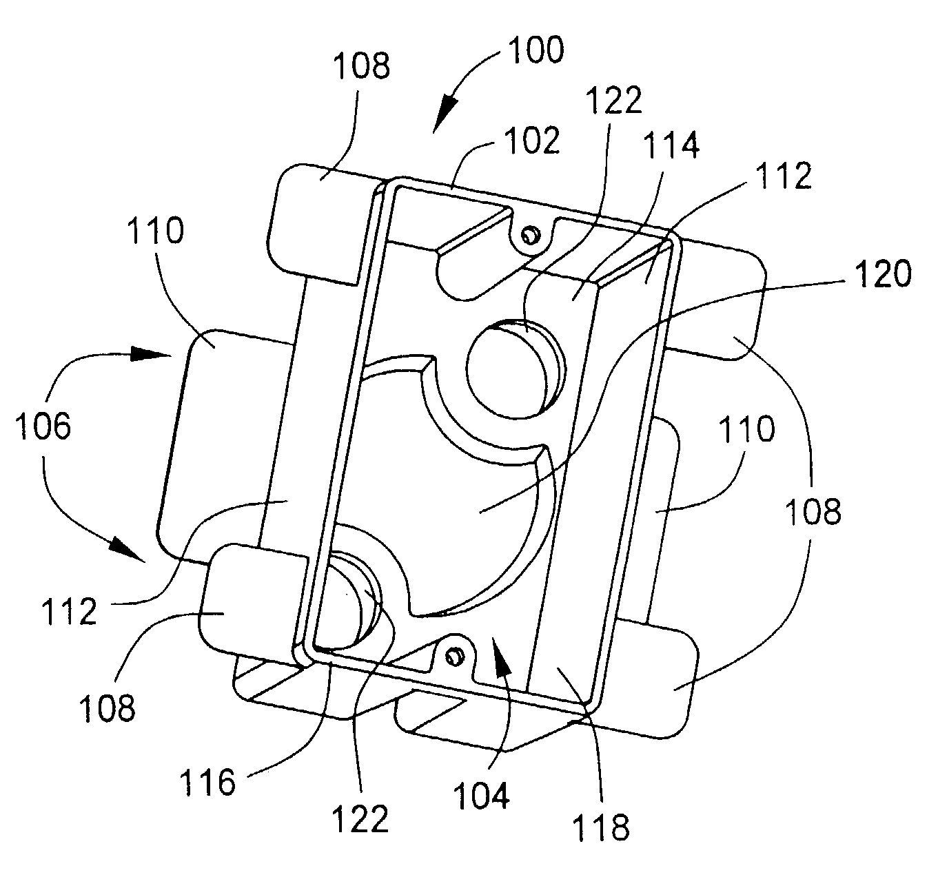
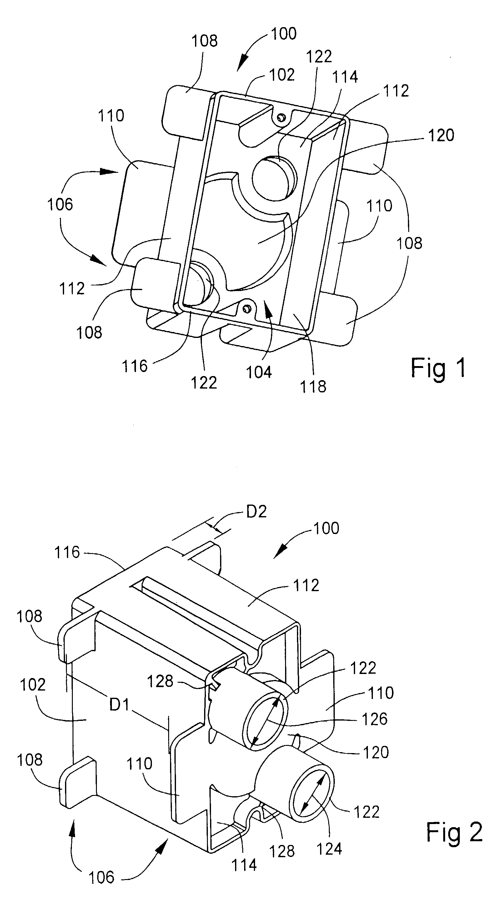
[0032]Turning to the drawings, wherein like components are designated by like reference numerals throughout the various figures, attention is initially directed to FIGS. 1 and 2. FIG. 1 is a front diagrammatic perspective view of an electrical box 100 designed in accordance with the present invention for use with insulated concrete form (ICF) building systems that utilize insulated forms to form concrete elements. In these building systems, the insulated forms are left in place after the concrete has been poured thereby creating an overall insulated concrete element that includes the concrete and the insulated forms. FIG. 2 is a rear diagrammatic perspective view of box 100.

[0033]In accordance with the invention, electrical box 100 includes a main body 102 having an electrical box cavity 104 for housing electrical outlets, switches, or electrical connections (not shown). Electrical box 100 also includes an attaching arrangement 106 for attaching the electrical box to an insulated fo...


PUM

PropertyMeasurementUnit
sizeaaaaaaaaaa
sizeaaaaaaaaaa
thicknessaaaaaaaaaa

Abstract

An electrical box for use with insulated concrete form building systems includes a main body having an electrical box cavity for housing electrical outlets, switches, and electrical connections. The insulated concrete form building systems utilize insulated forms to form concrete and the insulated forms are left in place after the concrete has been poured thereby creating an overall insulated concrete element that includes the concrete and the insulated forms. In accordance with the method and the arrangement of the invention, the electrical box includes an arrangement for attaching the electrical box to the insulated form without requiring the use of any additional fasteners.

Description

[0001]This is a Divisional application of prior application Ser. No. 10 / 151,909, filed on May 20, 2002, now abandoned, the disclosure of which are incorporated herein by reference.BACKGROUND OF THE INVENTION[0002]The present invention relates generally to electrical boxes for use in building construction that utilizes insulated concrete form building systems.[0003]Recently, many building systems have become available that utilize insulated concrete forms to form concrete walls, floors, ceilings and other structural elements. With these systems, concrete is formed into the desired walls, floors, ceilings, and other elements using concrete forms that are made from a rigid foam insulating material. These systems are commonly referred to as Insulated Concrete Form (ICF) systems. In these systems, the insulated concrete forms are left in place after the concrete is poured thereby creating an overall insulated concrete element that includes the concrete and the insulated forms. These syst...

Claims


Application Information

Patent Timeline
Patent Type & Authority Patents(United States)
IPC IPC(8): H01H9/02E04B5/48H02G3/08E04B5/00H01H9/00H02G3/00
CPCH02G3/121
Inventor MCCONAUGHY, DREW B.HEBIG, BRAD J.
Owner PLASTILOCK
Why Eureka
Try Eureka