
Wall Opening Form

a wall opening and form technology, applied in the field of forming openings, can solve the problems of dimensioned lumber buck construction that requires a significant amount of work, dimensioned lumber may be prone to rotting and water damage, and the opening is not as secure, so as to reduce the amount of bracing. , the effect of easy seclusion

Inactive Publication Date: 2009-08-06
QUAD LOCK BUILDING SYST
View PDF8 Cites 23 Cited by
  • Summary
  • Abstract
  • Description
  • Claims
  • Application Information

AI Technical Summary

Benefits of technology

[0011]The present invention provides a window buck that is resistant to water and rot and provides a surface that is easily securable to using nails, screws or other suitable fasteners. In addition, the present invention has a shape that retains the strength characteristics of wooden bucks thereby reducing required bracing and engages the surrounding concrete.

Problems solved by technology

A buck constructed from dimensioned lumber requires a significant amount of work to position within a wall cavity to form an opening therethrough.
Secondly, the assembled buck must be screwed to the forms within the opening to secure it in place.
This results in the opening not being as secure as is possible were the lumber to include a surface that positively engages the concrete.
In addition, dimensioned lumber may be prone to rotting and water damage should water permeate the wall thereby damaging the structure to which the window or door is secured.
The use of natural fiber-plastic composite material having such cross-sections, however, would not address some of the aforementioned difficulties with dimensioned lumber, namely, lack of positive engagement with the concrete.
Windows and doors are not as easily securable to the frame of Anderson et al. due to the material properties of the vinyl used in this construction.
Also, the use of a plastic-only extrusion in the frame of Anderson et al. results in a weaker structure than is possible by using a composite material of wood and plastic, for example.
However, it would be difficult to form the frame members of Anderson et al. from a wood and plastic composite material due to the complexity and thinness of the shape of the frame members.
It is known to be difficult to extrude wood and plastic composite materials through small die openings.

Method used


Image

  • Wall Opening Form
  • Wall Opening Form
  • Wall Opening Form

Examples


Embodiment Construction

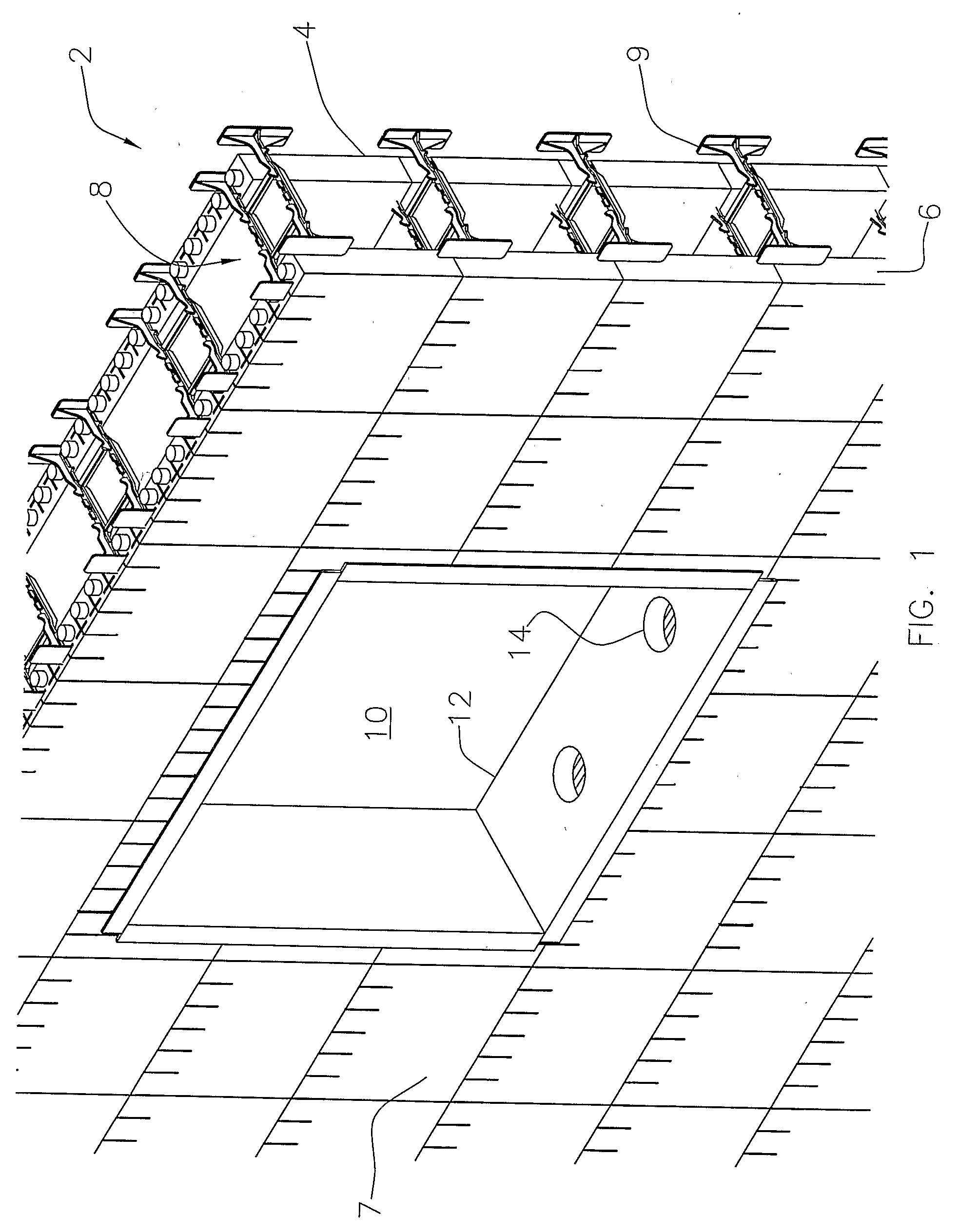
[0024]Referring to FIG. 1, an insulating concrete form wall is shown generally at 2. The insulating concrete wall comprises a pair of opposed first and second wall forms 4 and 6, respectively constructed of forming panels 7 and ties 9 forming a wall cavity 8 therebetween. The insulating concrete wall may include an opening 10 bounded by a wall-opening frame 12 according to a first embodiment of the invention. A window or a door may then be located within the opening 10 and secured to the wall-opening frame 12.

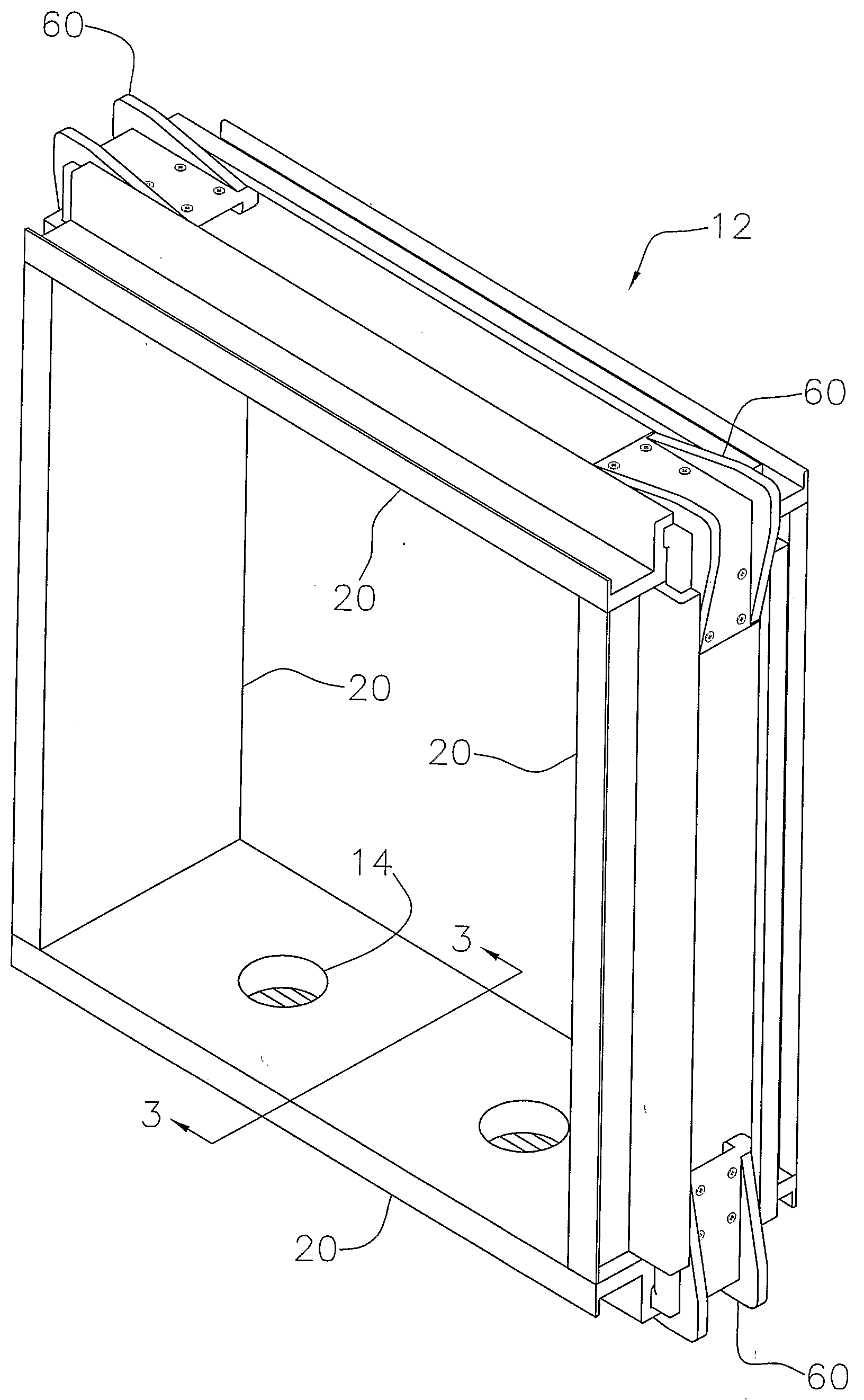
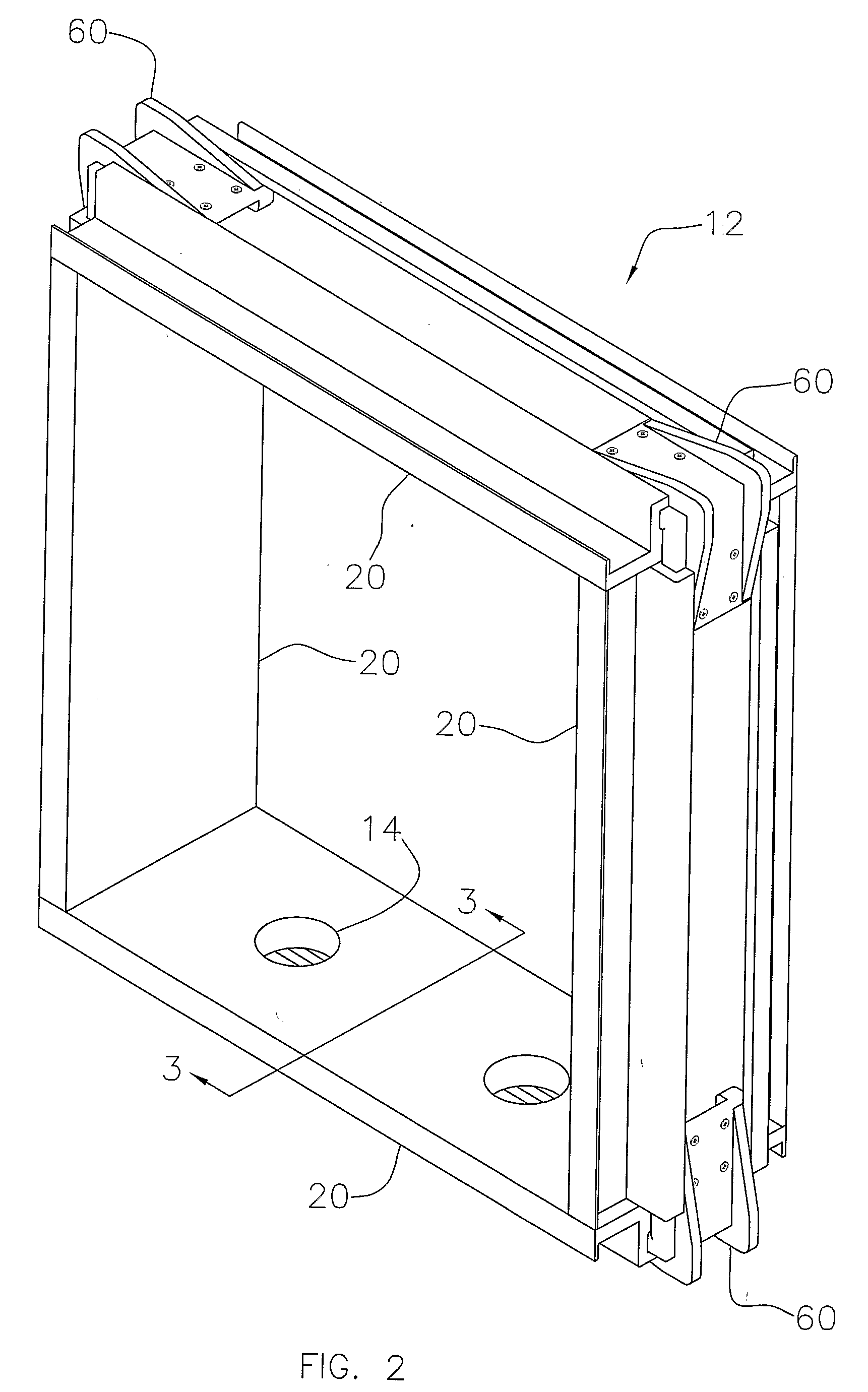
[0025]As shown in FIG. 2, the wall-opening frame 12 comprises a plurality of frame members 20 connected at adjacent ends to form a completed frame. The frame members 20 may be arranged in a rectangle as shown in FIG. 2 or in an inverted U-shape to form an opening for a door (not shown).

[0026]Now referring to FIG. 3, a cross sectional view of a frame member 20 of FIG. 2 is shown taken along the line 3-3. Each frame member 20 comprises a substantially elongate member as shown in ...


PUM


Abstract

Disclosed is a frame member for forming an opening through an insulating concrete form wall having opposed first and second forms. The frame member comprises an elongate member dimensioned to extend between the opposed forms. The elongate member is composed of a natural fiber plastic composite material having an opening forming surface and a wall forming surface and a pair of longitudinal retention fins extending from the wall forming surface. Each of the retention fins has a distal lip portion wherein the lip portions cooperate to form a hollow between the lip portions and the wall forming surface. Also disclosed is a frame for forming an opening through an insulating concrete form wall comprising at least three frame members and at least two corner connectors for connecting said frame members. The corner connectors comprise a bracket insertable into the hollows.

Description

BACKGROUND OF THE INVENTION[0001]1. Field of Invention[0002]The present invention relates generally to forming openings and in particular to providing a frame, frame members and framing kits for forming openings in insulating concrete form construction.[0003]2. Description of Related Art[0004]In the construction industry, a method known as insulating concrete form construction is well known. Insulating concrete form construction utilizes walls having a central cast in place concrete layer bounded by a pair of insulating forms. In insulating form construction, the insulating forms are typically comprised of forming panels which are positioned as a pair of spaced apart walls so as to form a wall cavity therebetween. The wall cavity may then be filled with concrete to form the completed wall. In this type of construction the forming panels may be left in place to provide additional insulating qualities to the wall.[0005]As is common with most forms of construction, it is frequently nec...

Claims


Application Information

Patent Timeline
IPC IPC(8): E04G15/02
CPCE04B2/8652E06B1/02E04B2002/8676
Inventor KUSTERMANN, HUBERT MAX
Owner QUAD LOCK BUILDING SYST
Learn More