Insulated concrete form method and system

a concrete and form method technology, applied in the field of freestanding residential construction, can solve the problems of increasing the difficulty and complexity of conduit installation, reducing the strength of the system, and using complicated bracing systems that are costly, cumbersome and time-consuming to assemble and disassemble,

Inactive Publication Date: 2009-11-17
BRADLEY SABINA
View PDF8 Cites 18 Cited by
  • Summary
  • Abstract
  • Description
  • Claims
  • Application Information

AI Technical Summary

Problems solved by technology

The ties create undesirable obstacles within the wall cavity during construction thereby increasing the difficulty and complexity in the installation of conduits, window and door framing as there is not a clear space between the forms.
Moreover, the ties are susceptible to failure and breakage thereby reducing the strength of the system.
Other types of prior art forming systems require the use of complicated bracing systems that are costly, cumbersome and time-consuming to assemble and disassemble.
Another shortcoming of the prior art is that the insulated concrete forms are typically higher priced, result in a poor surface appearance and are flimsy.

Method used


Image

  • Insulated concrete form method and system
  • Insulated concrete form method and system
  • Insulated concrete form method and system

Examples


Embodiment Construction

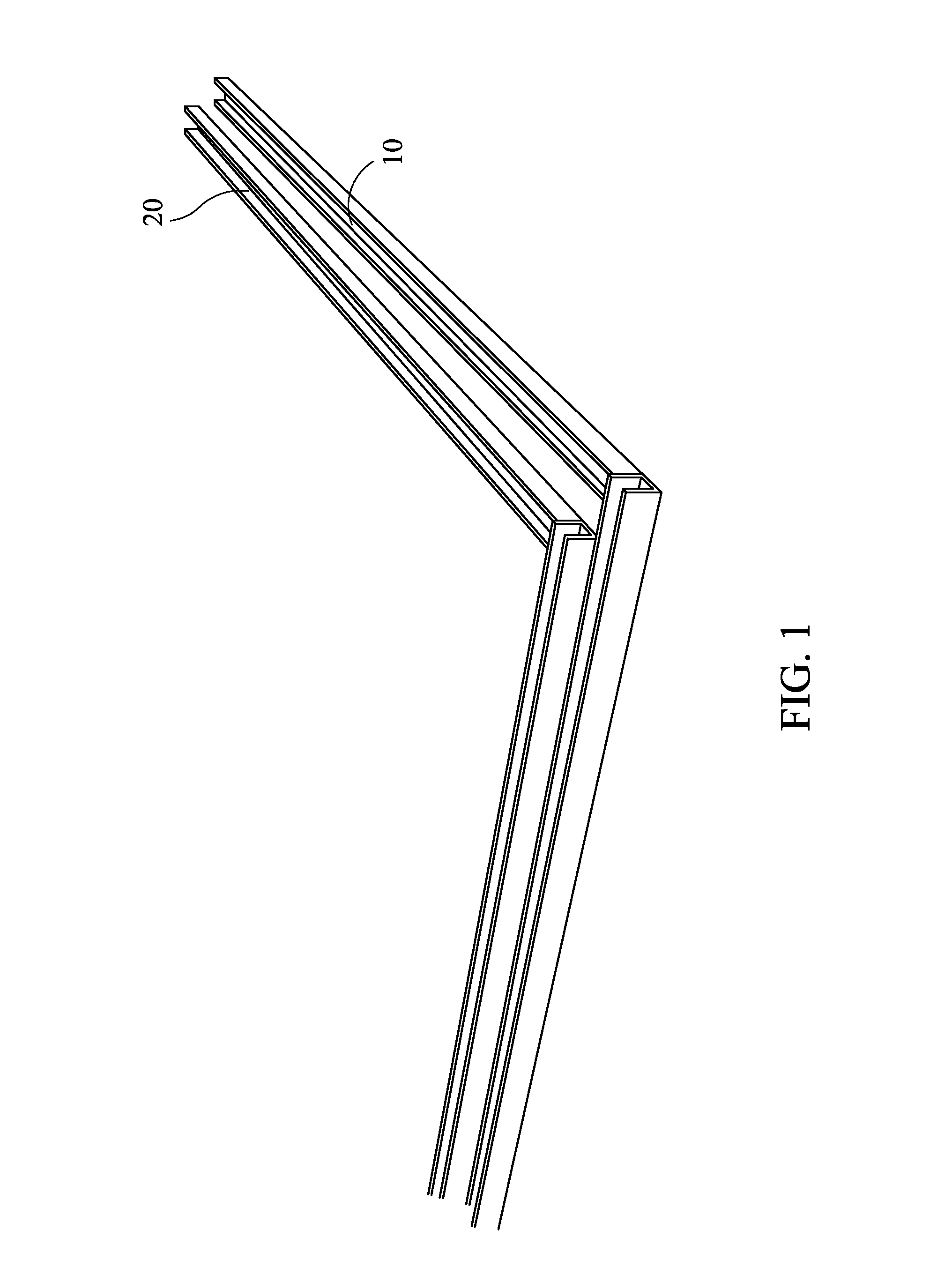
[0033]Referring to FIG. 1 shows the pair of bottom U-shaped channels secured to a concrete floor. An exterior bottom U-shaped channel 10 allows the bottom edge of the exterior foam sheet to be secured therein. The interior bottom U-shaped channel 20 is secured to the concrete slab an appropriate distance to accommodate the design width of the wall. The width can vary from six (6) to twenty (20) inches. The U-shaped channels 10, 20 are fastened to floor slabs using pneumatic nailers.

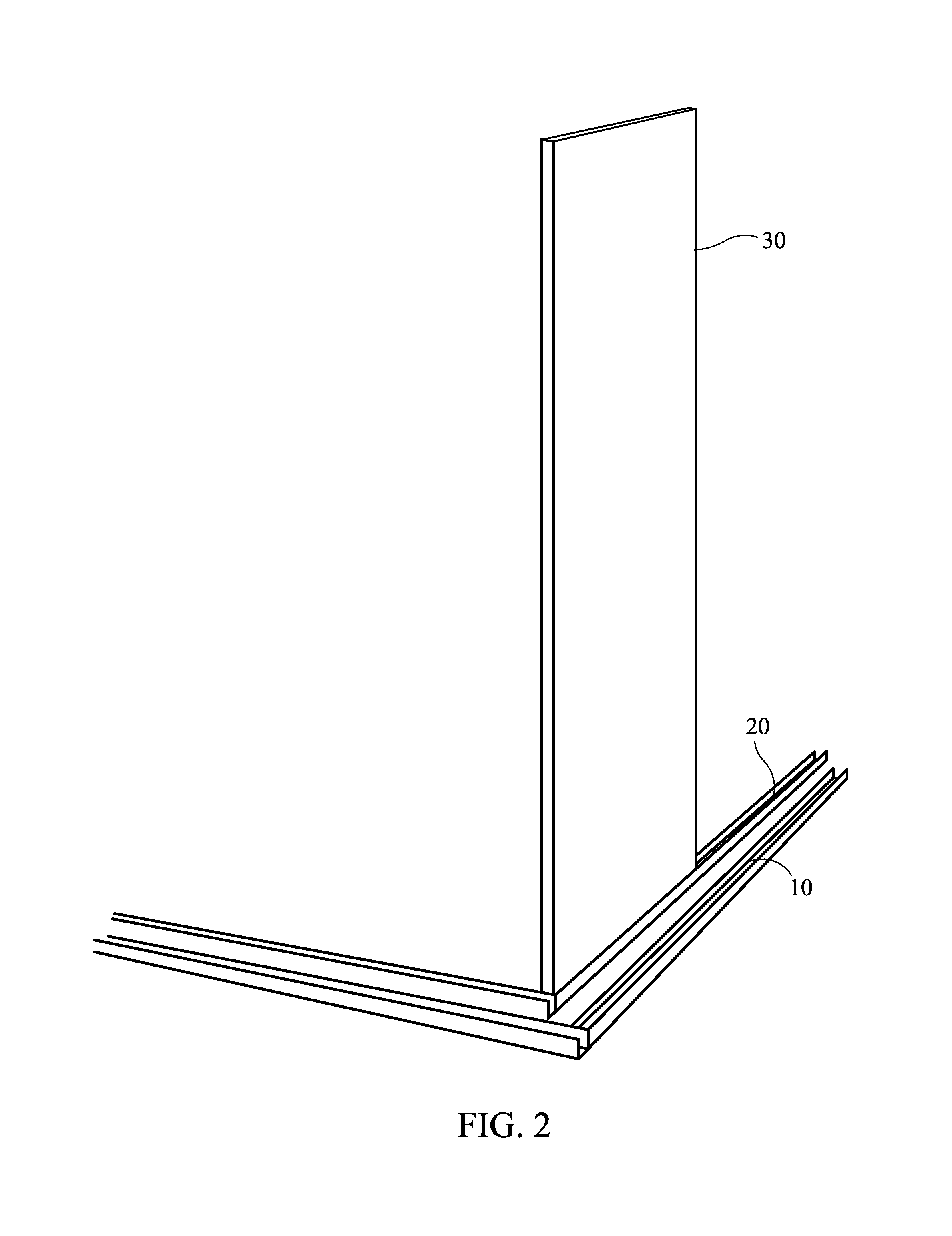
[0034]FIG. 2 shows interior foam sheet 30 installed within interior bottom U-shaped channel 20. Once a foam sheet is placed in the bottom U-shaped channel, the top U-shaped channel 50 is placed on the top edge of foam sheet 40 as shown in FIG. 3. Foam sheets 30, 40 vary in size from four (4) feet wide to eight (8), ten (10), twelve (12) or twenty-four (24) feet in length and are made of polystyrene. The thickness of foam sheets 30, 40 vary from one (1), two (2) or four (4) inches and remain with the struc...


PUM


Abstract

An insulated concrete form system having a pair of bottom U-shaped channels secured to a concrete slab that serve as a footprint for a concrete wall. Exterior and interior foam sheets are aligned within the bottom U-shaped channels that define the wall. Top U-shaped channels are slipped over a top edge of the foam sheets. A plurality of strongbacks are used to provide structural support for the foam sheets during a concrete pour of the wall. The strongbacks each have a pair of hangers adapted to be secured over the top U-shaped channels to secure the strongbacks to the foam sheets. A top wall spacer is used to join a strongback on one side of the wall cavity to a strongback on a second side of the cavity to resist pressure exerted outward on the foam sheets during a concrete pour to form the wall.

Description

BACKGROUND OF THE INVENTION[0001]1. Field of the Invention[0002]The present invention relates generally to the construction of free-standing residential structures, and more specifically to a novel insulated concrete form method and system.[0003]2. Description of the Prior Art[0004]The prior art concrete form systems require the use of numerous ties to secure the forms in place. The ties create undesirable obstacles within the wall cavity during construction thereby increasing the difficulty and complexity in the installation of conduits, window and door framing as there is not a clear space between the forms. Moreover, the ties are susceptible to failure and breakage thereby reducing the strength of the system. Other types of prior art forming systems require the use of complicated bracing systems that are costly, cumbersome and time-consuming to assemble and disassemble.[0005]Accordingly, what is needed in the art is an insulated concrete form system that reduces or eliminates the...

Claims


Application Information

Patent Timeline
Patent Type & Authority Patents(United States)
IPC IPC(8): E04C1/00E04B2/00E04G11/06E04G21/26
CPCE04B2/8605E04G17/002E04B2002/8688
Inventor BRADLEY, SABINA
Owner BRADLEY SABINA
Why Eureka
Try Eureka